The main point though is that when we look at the curve it may depend how it was drawn as to how we view the knee. But changing the scale of the x axis changes the view, which should not happen. We dont switch zener part numbers just because we change the scale of the axis.
It's a rather arbitrary judgement call but in most cases I'd probably opt for something in the vicinity of the red line, roughly where the increase in conductivity per applied volt is greatest. But there are situations where I'd be most interested in what the Zener is doing around the green line or even below, and situations where I'd want to know what it's doing around the violet line or even higher.
Well ok so far there were 8 votes for red and 2 for violet and 0 for green.
It looks obvious that green isnt right, but i think i can redraw the graph to make green look right.
Note that if you chose red then you should look at the second drawing. That shows how the apparent knee changes and it should not.
We dont change zener part number just because we draw the graph with a different scale.
Anyway, the best definition appears to be the point where the curvature is maximum. You can look into that though and see what you think.
That means that we no longer think of the knee as a point were we see on the graph, but a mathematical point.
In this case, the violet line meets the curve at the point of least curvature. And that should be true for any drawing because the curvature does not depend on scale.
I would still like to hear other ideas too though.
I am trying to work this into a curve fit for a particular model zener. It may end up being an iterative process though and i was trying to avoid that. Given some voltage and current levels on the curve, the model can be fit pretty easy, but it does not mean the 'knee' defined above is any voltage we can enter and have the params spit out, it looks like it has to be iterative. I am looking for a way around that.
For their BZX79C Zener diodes, NXP (used to be called Philips) do not list the knee voltage but I think they did many years ago.
They have the voltage rated when the current is 5mA for the low voltage ones up to 24V. They show "differential resistance" at the rated 5mA which is low, and show it at 1mA when it is up to 10 times higher. The differential resistance can be used to determine the voltage regulation.
The zener voltage is the voltage at a given test current.
If we were to take a nominal test current of 40mA, this gives our DUT a zener voltage of approx. 7.1V.
Hence, choose your current and that is your breakdown voltage (and not the knee voltage).
Well one of the points i am trying to make is that these drawings are not enough, except for the "IEC" one which might make sense i'll have to look into that. That looks like where the two slopes meet which might be mathematical enough.
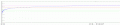
Here is a third drawing that makes it look like maybe like the green line is the line that intersects the blue diode curve at the knee. See what you think. I had to edit this one by hand a little because when i stretched the x axis the curve got a little block looking. You can see what i am talking about though i think if you look at all three drawings and compare. It looks like the knee 'moves' as the x axis scale changes, which it should not even with a rough definition. I think that is what most of us always thought was the 'knee' because it looks like where the knee is of a person sitting in a chair.
Well, I'm colorblind but the low line looks like the 45° point for one definition and the top line where the "Knee" flattens out and becomes a constant slope for another definition.
Well, I'm colorblind but the low line looks like the 45° point for one definition and the top line where the "Knee" flattens out and becomes a constant slope for another definition.
Thanks. But you see how i made the knee seem like it moved three times with three different drawings? Yet it is the same curve same diode each time. So referring to a graphic alone can not solve the problem it must be mathematical.
I made a misstatement previously though, one math definition would be the knee is at the point of maximum curvature not minimum, and i edited that post now too. This makes some sense intuitively also because we think of the 'knee' of a person sitting down as the place where the leg bends most sharply, and that is the point of maximum curvature.
I would not doubt it though that different manufacturers define this differently too because there might not have been any real standard long time ago when zeners were first being made.
One of my goals is to incorporate this into the curve fitting algorithm for a zener, maybe for a regular diode too as we see the same kind of curve there too with a 'knee' also.
It also looks like the knee may not be as important anyway because a real circuit design goal is really only indirectly associated with the knee and is more associated with the more flat horizontal section in most cases. Also, as shown in the three graphics in this thread, it may be hard to pick the knee as a curve fit point because it's hard to spot looking at any one graphic. It's simpler just to pick three more relevant points.
You cannot determine knee voltage by visual inspection.
One man's knee is another man's ankle.
What are the scales on the graph? (Is it linear, semi-log, or log?)
One way is to draw a line on the straight part of the curve. (The question is linear or log scale?)
Then look at where the line intersect the axis. (Next question: which axis?)
Or draw two lines on both sides of the curve and look at the intersection. (What scale: linear, semi-log, or log?)
Another method is when one of the lines rises or falls by a given amount, as in -3dB or -6dB as in Bode plots, or 0.7 or 0.5.
I think that's true.
The exact location of the Zener "knee" is generally not of interest for normal circuit design.
The typical parameters of interest are the Zener voltage at a desired operating current, and the Zener dynamic resistance (a measure of it's regulation accuracy).
I think that's true.
The exact location of the Zener "knee" is generally not of interest for normal circuit design.
The typical parameters of interest are the Zener voltage at a desired operating current, and the Zener dynamic resistance (a measure of it's regulation accuracy).
Well the other view is that the knee should indicated something comparative about two different zeners. But if everybody defines it differently this wont be possible. Compare this idea to the cutoff frequency of a low pass filter.
There would still have to be other specs too of course.
Well the other view is that the knee should indicated something comparative about two different zeners. But if everybody defines it differently this wont be possible. Compare this idea to the cutoff frequency of a low pass filter.
There would still have to be other specs too of course.
In my very limited experience with Zeners, it seems like the available nominal values are spaced out far enough that the small differences you're pointing out would be negligible.
In other words, if I want a 5V clamping action, it's not like I get to choose between a variety of "5V" Zeners and find myself wishing they all used a standard methodology with greater precision, listing 4.97 vs 5.05, etc. In my experience, I end up choosing between 4.7 and 5.1V options. For any more detail, I have to read the datasheet for the parameters that actually matter in my given situation. I'm not sure a more precise or consistent Zener knee description would help with this process.
Yes i agree. What i was hoping for was maybe too great.
I had hoped to allow the user to set the knee voltage as one of the parameters in a zener model. But with all the confusion it may not work out in the long run.
What i found was that right now i can set three different voltage parameters and get a good fit to though three voltages, but one of the voltages has to be with low current while the other two more or less should be with higher current. For example i chose to start with current levels 0.001, 0.010, and 0.100 amps. But now i have to choose three voltage levels for each current level. I am looking at the best way to choose those voltages and i thought if there was any common ground with zeners maybe the knee voltage could be the middle one.
Still looking at this however and have not settled on anything yet.
Maybe a different approach is needed...
Repectfully MrAl....What problem are you trying to solve that isn't already solved using current spice modelling methods? Or maybe your just experimenting?
Maybe a different approach is needed...
Repectfully MrAl....What problem are you trying to solve that isn't already solved using current spice modelling methods? Or maybe your just experimenting?
What is your metric for "better"? For instance, given the statistical nature of real devices, a marginal improvement of fitting a particular, single diode's characteristic may not be viewed as "better" if it comes in significantly increased computational costs.
 Facebook
 Google
 GitHub
 Linkedin
")