Facebook
 Google
 GitHub
 Linkedin

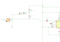
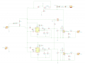
Bolting two opamp outputs (plus an external input) directly together without build-out resistors probably will compromise audio quality. Basically, each amp's output looks like a dead short to the other outputs. Technically, it looks like a very low impedance to a varying voltage source, but that still is not something these opamp outputs were designed to drive.. There is a reason everything is joined together through 10K resistors in the original schematic.
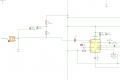
There is not enough power supply decoupling for the circuit elements. If you look at the datasheets for the four components, you will see that each has recommended decoupling shown. Those capacitors must be as close as possible to the respective components' power pins.
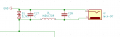
To bias the mics from a 5 V supply, I would start with 2.2K. A better way is to decouple the 5 V through a 100 ohm resistor and a 0.1 uF and 100 uF capacitor, and from there through the 2.2 K to the mic input.
ak
There is not enough power supply decoupling for the circuit elements. If you look at the datasheets for the four components, you will see that each has recommended decoupling shown. Those capacitors must be as close as possible to the respective components' power pins.
To bias the mics from a 5 V supply, I would start with 2.2K. A better way is to decouple the 5 V through a 100 ohm resistor and a 0.1 uF and 100 uF capacitor, and from there through the 2.2 K to the mic input.
ak
Last edited: