Intercom Circuit design - SXS Intercom

Thread Starter

eyeTech

Joined Dec 12, 2023
11
Hi all,

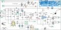
I am attempting to build an Intercom for my SXS and need help choosing the right components—mainly the Capacitors. I know different caps are better in some uses but I've hit my limit on identifying what they are used for in this circuit and what type I should use.

I'm building the circuit from this blog post: https://www.eeweb.com/aviation-intercom/

The list of caps are:
470nF - 1
100nF - 3
470nF - 1
1.5nF - 1
100uF 16v - 2
10uF 16v - 4
22uF 16v 1
220uF 16v - 1

Hopefully this is the right place to post and thank you.
 

Attachments

Irving

Joined Jan 30, 2016
5,040
Welcome to AAC!

All of the capacitors showing + & - and a voltage rating are Electrolytic Capacitors, either polymer or aluminium. If you are building this on a PCB you need to check physical lead spacing to ensure you get the right physical size. If you can't get the specified voltage, a higher rating is ok but may be physically larger. Get good quality parts, avoid cheap chinese ones.

For the remaining 1.5, 100 & 470nF devices I'd go for ceramic or polyester parts but again check lead spacing as there are many size options. Generally these would be rated at 50 or 63v by default.

What transformers are you using?
 
Last edited:

MisterBill2

Joined Jan 23, 2018
27,258
Welcome to AAC. Post #2 is correct. The purpose of the optos and relays is not perfectly clear though. Is it to disable whatever microphone is not selected?? The LM386 is not very powerful so the speakers will not be very loud. Not sure if that matters or not.
 

LowQCab

Joined Nov 6, 2012
5,101
What type of performance do You expect from this Project ?
Something that just kinda-sorta-maybe works ?,
or a Circuit that has built-in Squelch, Compression, and mild-Clipping
that can reliably and clearly cut through heavy outside Noise ?
.
.
.
 

AnalogKid

Joined Aug 1, 2013
12,076
This is the perfect forum for your type of question. But - the circuit needs some work.

Among other things, the DC power input goes through a noise filter choke, but then has *zero* filtering and decoupling capacitors to return its impedance back to near-zero.

The mute system seems overly-complex and a bit strange.

It isn't stated in the article, but I assume the circuit is meant for dynamic mic elements, not electret, since there is no DC bias for the mic inputs.

The 2-transistor mic preamp is cute, but an opamp will have much better input summing and isolation, and a much lower output impedance to drive all of the outputs.

*Any* resistance in series with an LM386 power pin is not a good idea.

For better muting, use an opto-coupler with FET outputs.

And the 100K resistors in parallel with the pots make no sense at all.

ak
 

MisterBill2

Joined Jan 23, 2018
27,258
I do wonder about the direct coupled two stage audio amp. DC coupling requires setting the operating points just right,which might take some work. And I agree that a low noise op-amp would be a better choice. That part may have come from a HiFi circuit collection.
Now I realize that the output is to headphones the LM386 is a reasonable choice, but not the only one.
And with a total of five volume controls adjusting may take some effort. I recommend separate amplifiers , one for each headset, because not all folks have the same hearing response. Squelch and possibly volume compression would be interesting, but both the radio and the computer already have squelch, and the microphones are already push-to-talk, so squelch will not add any benefit.
Actually, I do not understand the whole scheme for keying the radio transmit, although it seems that it is intended to mute whichever microphone is not being used to key the radio. So an explanation of the intended functioning will clarify the intended operation, as it seems a bit complex.
.
 

AnalogKid

Joined Aug 1, 2013
12,076
I do wonder about the direct coupled two stage audio amp. DC coupling requires setting the operating points just right,which might take some work.
Not as much as you might think. The 2.2K feedback resistor from the Q2 collector to the Q1 emitter both sets the stage gain and stabilizes the DC operating point.

More stuff:

The squelch circuit is just wrong. When one of the opto's conducts, it puts an 11.5 *volt* (not millivolt) transient into the signal. Both the preamp and the output amp will saturate (clip) but it still will be an ear-damaging blast.

Also the two 100K resistors at the mic inputs are - questionable? That value is too large to bias an electret microphone cartridge, and too small to work with a dynamic mic. Any DC is too much DC through a dynamic mic coil. I suppose it could be a bias voltage for a true condenser mic, but that usually is a much higher voltage; and then the preamp stage gain is way too low.

Sure would be nice if the schematic had reference designators for all components.

ak
 
Last edited:

Thread Starter

eyeTech

Joined Dec 12, 2023
11
Thanks for the input guys!

Ill be honest, I'm a bit out of my depth with this one. I could omit to tie it into a radio as i don't have any plans for that at this time. just figured it may be nice to have in the future. I'm planning on using a cheap aviation-style headset with this. Squelch may be nice to have but I'm not sure it's necessary as the commercial product for this doesn't appear to have it. (Rugged Radios)

It seems that most aviation headsets have a volume knob on them so you could adjust it from there.

I am hoping it has enough volume to overcome fairly loud engine noise. But keep in mind the headsets do passively cut down on noise.

I could eliminate the mic muting and radio switches. Would I just remove the 2.2k resistors and down? I would just leave the radio audio in and if a transmission is heard i can reply with the Radiomic directly.

As for the mic resistors, what would you reccomend?

Also for filtering capacitors, would the 100uf at the far left be doing that? or what would be best there?


Headsets:
https://www.amazon.ca/gp/product/B09DG1PKVH/ref=ppx_yo_dt_b_asin_title_o01_s00?ie=UTF8&psc=1
attached is the KiCad file I've been working on.

Thanks again,
 

Attachments

Thread Starter

eyeTech

Joined Dec 12, 2023
11
Also, here is a list of components i was planning on using.


SHOPPING CART
This is not an invoice​
15-Dec-23 14:15:46​
Mouser #
Mfr. #
Manufacturer
Customer #
Description
RoHS
Lifecycle
Order Qty.
Price (CAD)
Ext.: (CAD)
1​
42TL013-RC​
42TL013-RC​
Xicon​
Audio Transformers / Signal Transformers XFMR 1KCT/8CT​
RoHS Compliant​
5​
$3.07​
$15.35​
2​
512-BC548BTA​
BC548BTA​
onsemi​
Bipolar Transistors - BJT NPN 30V 100mA HFE/450​
RoHS Compliant​
2​
$0.479​
$0.96​
3​
637-BC558C​
BC558C​
Diotec Semiconductor​
Bipolar Transistors - BJT BJT, TO-92, 30V, 100mA, PNP​
RoHS Compliant​
2​
$0.348​
$0.70​
4​
782-ILD2​
ILD2​
Vishay​
Transistor Output Optocouplers Phototransistor Out Dual CTR >100%​
RoHS Compliant​
2​
$1.80​
$3.60​
5​
511-1N5822​
1N5822​
STMicroelectronics​
Schottky Diodes & Rectifiers Vr/40V Io/3A BULK​
RoHS Compliant By Exemption​
2​
$0.609​
$1.22​
6​
637-1N4004​
1N4004​
Diotec Semiconductor​
Rectifiers Diode, DO-41, 400V, 1A​
RoHS Compliant By Exemption​
4​
$0.305​
$1.22​
7​
594-5063JD10K00F​
MBA02040C1002FC100​
Vishay​
Metal Film Resistors - Through Hole .4watt 10Kohms 1% 1/8watt body size​
RoHS Compliant​
5​
$0.667​
$3.34​
8​
704-CTX1000-1-52-R​
CTX1000-1-52-R​
Eaton​
Power Inductors - Leaded 1000uH 2.1A 0.64ohms Vertical Mount​
RoHS Compliant​
1​
$11.80​
$11.80​
9​
926-LM386N-1/NOPB​
LM386N-1/NOPB​
Texas Instruments​
Audio Amplifiers LOW VLTG AUDIO PWR AMP​
RoHS Compliant​
2​
$1.84​
$3.68​
10​
523-ACJS-MHDE​
ACJS-MHDE​
Amphenol​
Phone Connectors 1/4 in. Dual Phone Jack Stereo Metal​
RoHS Compliant​
6​
$6.19​
$37.14​
11​
490-SJ1-3554NG​
SJ1-3554NG​
CUI Devices​
Phone Connectors Audio Jacks​
RoHS Compliant​
4​
$1.15​
$4.60​
12​
313-1530F-5K​
RV16AF-20-15K-A5K-3LA​
Alpha (Taiwan)​
Potentiometers Audio Knurled 5K PC Mount​
RoHS Compliant​
5​
$2.33​
$11.65​
13​
581-KGM32LR72A474MU​
KGM32LR72A474MU​
KYOCERA AVX​
Multilayer Ceramic Capacitors MLCC - SMD/SMT 100V .47uF X7R 1210 20%​
RoHS Compliant​
New Product​
5​
$0.725​
$3.63​
14​
80-C0603C104K1RAUTO​
C0603C104K1RACAUTO​
KEMET​
Multilayer Ceramic Capacitors MLCC - SMD/SMT 100V 100000pF 10% X7R 1608 AEC-Q200​
RoHS Compliant​
New Product​
15​
$0.297​
$4.46​
15​
80-C0402C152KCRAUTO​
C0402C152KCRACAUTO​
KEMET​
Multilayer Ceramic Capacitors MLCC - SMD/SMT 500V 0.0015uF X7R 0402 10% AEC-Q200​
RoHS Compliant​
New Product​
3​
$0.508​
$1.52​
 

AnalogKid

Joined Aug 1, 2013
12,076
Also for filtering capacitors, would the 100uf at the far left be doing that? or what would be best there?
The 100 uF / 16 V cap at the far left filters only the DC voltage going to the very problematic mute and microphone bias circuits. With the 1.5 K resistor, it forms a lowpass filter with a 1 Hz corner frequency. No change needed, that is one part of the schematic that is correct.

ak
 

Irving

Joined Jan 30, 2016
5,040
Careful - the MLC Capacitors youve selected are surface mount not through-hole like your other components - was that intentional? Also item 15 is a 0402 part - thats 1.2mm x 0.6mm, not suitable for hand soldering

Try these - all 50v ceramic disc, 5mm lead spacing
470n 810-FG28X7R1H474KRT0
100n 594-K104K10X7RF53H5
1.5n 594-K152K15X7RF5TH5
 
Last edited:

Thread Starter

eyeTech

Joined Dec 12, 2023
11
Careful - the MLC Capacitors youve selected are surface mount not through-hole like your other components - was that intentional? Also item 15 is a 0402 part - thats 1.2mm x 0.6mm, not suitable for hand soldering
I have hotair capabilities and only need to put on 1 of them. Hence why i was buying 3 and figured id try my luck.

Ill look at larger options tho.


Im a little lost on the microphone bias. it does seem like this headset and most others are electret microphones. what would the best option be? should I look at something like this? https://www.adafruit.com/product/1063
 

AnalogKid

Joined Aug 1, 2013
12,076
1. Where are you located?

2. How much do you want to buy versus build, and what is your build skillset. In a board full of PTH components, a couple of SMT caps doesn't seem to me like a good move.

The article mentions that the circuit works with noise-cancelling headphones. These have a small power amp built-in, and do not need much drive current. Regular headphones need much more, which raises a question about the output transformers. A step-*up* output transformer is a rare thing, and I've never seen one in an intercom. It reduces the available output current, not good. If you have a datasheet or site link for the headset you intend to use, we can evaluate it versus this circuit.

Consider starting from scratch. As you know, microphone preamp boards are available. There is a different module that adds an audio compressor to the preamp function. There are LM386 power amp boards and relay boards, for less than you can buy the parts for. Better optocouplers fix the mutes. That leaves the two line-level inputs and the mixer function.

Is this a one-off perf board project, something headed for a pc board, other - ?

ak
 

Thread Starter

eyeTech

Joined Dec 12, 2023
11
I'm located in alberta, Canada.

Commercial units are $900 and up so I figured it could be built for much less. I figured it would be a bit of a project to learn board design and save a few $

It is a 1 off project but could make a few extra to sell to friends after. I was planning on making a PCB but may end up on a perf board.

The headsets i plan to use are not ANR. Just passive headsets. I was going to remove the ANR portion of the circuit
Clone of these: https://www.ruggedradios.com/products/rugged-air-ra200-general-aviation-pilot-headset


Maybe a couple boards based off the SSM2167 would work? How could mixing work?
 

Irving

Joined Jan 30, 2016
5,040
If I was building this from scratch I'd look at dedicated chips eg MAX4466 mic preamp (1 per mic input) MAX9722 headphone amp (1 per headphone out)... eg per user... and about $10 per channel for parts..

1702676141401.png1702676280821.png

Then couple all channels together with a simple resistive mixer.

130mW out is more than enough drive for your proposed headphones.

The SHDN input on the preamp gives a simple pop-free PTT solution with or without optoisolators.
 
Last edited:

Thread Starter

eyeTech

Joined Dec 12, 2023
11
On the note of starting from scratch, am I crazy to think this would work:

2 of these mic amps with Pots added to control gain and noise gate:
https://www.amazon.ca/gp/product/B07TWC2MQB/ref=ewc_pr_img_3?smid=A1HVCTHF5PHDZF&psc=1

2 of these headphone drivers for headphone output:
https://www.amazon.ca/gp/product/B09KGXDBGC/ref=ewc_pr_img_2?smid=A30QSGOJR8LMXA&psc=1

1 of these buck converter for power:
https://www.amazon.ca/gp/product/B07T5X5LSH/ref=ewc_pr_img_1?smid=A3JJM7S8SDXVXM&th=1

and add this for bluetooth just for fun:
https://www.amazon.ca/dp/B09LDBJ2JW?psc=1&ref=ppx_yo2ov_dt_b_product_details

Could i just connect them together and use the mic gain and bluetooth volume to mix the signals?


I know ive gotten away from building my own pcb but this looks too simple to work?
 

AnalogKid

Joined Aug 1, 2013
12,076
A buck regulator is an overpowered, unnecessarily complex noise source in this application. Better to stay with the LM386 for the power amps because they run off of the system 12 V with no regulation - and no regulator heat. If an audio module needs a lower voltage, the current requirement will be so low that a simple zener diode or 78L05 can do the regulation.

The mic preamps are interesting. SSM is the king of audio compression, but the modules do not have places indicated for the two adjustment resistors. Also, the intercom system already is push-to-talk, the ultimate noise gate. Throwing another, electronic one into the mix is an unnecessary complexity. A preamp module with a compression function would be better.

I called the Rugged people - they are closed for their season party. The published data is not enough to pin a design on.

ak
 
Last edited:

Thread Starter

eyeTech

Joined Dec 12, 2023
11
Well I'm gonna take a stab at a new board with 2 lm386 for the headsets and ssm2167 for each mic.

I'll update you guys with it later to see how I did. Might take me a couple days lol.
 

Thread Starter

eyeTech

Joined Dec 12, 2023
11
Well, here is my attempt. I think I should include filtering to reduce noise on the 12v from the sxs, but I'm not sure how best to do that.

One thing I'm not sure of is Mic Biasing. I have decided to try a different headset as the first one came in and sounds awful.
New one is: https://www.retevis.com/ehg001-noise-reduction-general-aviation-headset-for-pilots-us


Speaker
TypeDynamic speaker
Impedance150 Ω(300 Ω)
Sensitivity119±3dB At 1K Hz/IEC318, 547 m
Resonance freq / ±20%Hz
Frequency respond20-20KHz
Rated input power80mW
Maximum input power80mW
Microphone
Microphone SpecificationBidirectional
Sensitivity Range-35±2dB
Impedance Max2.2KΩ@1KHz
Frequency50-10KHz
Current Consumption Max500uA
Operation Voltage Range1.0-10V
Max Sound pressure Level110dB


Intercom v2.png
 
Top