Intercom Circuit design - SXS Intercom

AnalogKid

Joined Aug 1, 2013
12,241
Bolting two opamp outputs (plus an external input) directly together without build-out resistors probably will compromise audio quality. Basically, each amp's output looks like a dead short to the other outputs. Technically, it looks like a very low impedance to a varying voltage source, but that still is not something these opamp outputs were designed to drive.. There is a reason everything is joined together through 10K resistors in the original schematic.

There is not enough power supply decoupling for the circuit elements. If you look at the datasheets for the four components, you will see that each has recommended decoupling shown. Those capacitors must be as close as possible to the respective components' power pins.

To bias the mics from a 5 V supply, I would start with 2.2K. A better way is to decouple the 5 V through a 100 ohm resistor and a 0.1 uF and 100 uF capacitor, and from there through the 2.2 K to the mic input.

ak
 
Last edited:

MisterBill2

Joined Jan 23, 2018
28,090
I have no critical words about the circuit. The additional decoupling suggested for the mic bias may offer a benefit, depending on the actual electrical noise level.
I do have a concern as to the durability of that four circuit connection scheme for the headset. that is a cheap consumer grade system that is not good enough for aircraft application. Certainly there is no less expensive 4 circuit scheme available. Both LEMO and UDO offer connectors to provide the same function and never break. REliability may matter in an airplane comm system.
 

Irving

Joined Jan 30, 2016
5,195
A few comments:

The GND (pin 1) of the SSM2167 chip should be connected directly to GND and not via a capacitor C5/C6.

Consider a CLC pi filter on DC input jack pin 1 as aircraft electrics v. noisy. Also a 15v transient suppressor (TVS) diode to ground.

Power LM368s from 12v and add a load more decoupling direct to pin 6 - 100u in parallel with 100n.

Put 100n in parallel with each of C8 & C9

Gate (pin 7) of SSM2167 is 5k RV to VDD only, not to GND. Connect 3 to 2 on RVGateX. This input is a current sourced from VDD not a voltage.

Similarly, Comp (pin 8) is 5k RV to VDD only, not to GND. Connect 3 to 2 on RVCompX. This input is a current sourced from VDD not a voltage.

Put a 1k resistor in line from each SSM2167 output at pin 9.

No PTT function/provision?
 

Thread Starter

eyeTech

Joined Dec 12, 2023
11
Just to clarify this is NOT going in an aircraft. It is for my UTV a Can-am Maverick. If something fails it is 100% not critical. If I had the money for a plane I'd be able to buy the commercial thing!

Bolting two opamp outputs (plus an external input) directly together without build-out resistors probably will compromise audio quality. Basically, each amp's output looks like a dead short to the other outputs. Technically, it looks like a very low impedance to a varying voltage source, but that still is not something these opamp outputs were designed to drive.. There is a reason everything is joined together through 10K resistors in the original schematic.

There is not enough power supply decoupling for the circuit elements. If you look at the datasheets for the four components, you will see that each has recommended decoupling shown. Those capacitors must be as close as possible to the respective components' power pins.

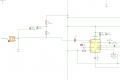
To bias the mics from a 5 V supply, I would start with 2.2K. A better way is to decouple the 5 V through a 100 ohm resistor and a 0.1 uF and 100 uF capacitor, and from there through the 2.2 K to the mic input.

ak
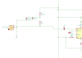
I added 3 10k resistors. the datasheet for SSM2167 says it needs more than a 5k load. if the Bluetooth module is louder than the mics could I decrease them to 5k?

I added decoupling as Irving suggested. I couldn't find much in the datasheets with other recommendations.

As for the bias, I think I understood you correctly. If not please correct me.
1703011039585.png


I have no critical words about the circuit. The additional decoupling suggested for the mic bias may offer a benefit, depending on the actual electrical noise level.
I do have a concern as to the durability of that four circuit connection scheme for the headset. that is a cheap consumer grade system that is not good enough for aircraft application. Certainly there is no less expensive 4 circuit scheme available. Both LEMO and UDO offer connectors to provide the same function and never break. REliability may matter in an airplane comm system.
I haven't 100% decided on connectors but I do agree with you. The headset I chose comes with dual GA plugs. So most likely use PJ-055, and PJ-068. but may end up with cables out of the box and inline connectors so that I can try to waterproof it.


A few comments:

The GND (pin 1) of the SSM2167 chip should be connected directly to GND and not via a capacitor C5/C6.

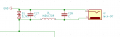
Consider a CLC pi filter on DC input jack pin 1 as aircraft electrics v. noisy. Also a 15v transient suppressor (TVS) diode to ground.

Power LM368s from 12v and add a load more decoupling direct to pin 6 - 100u in parallel with 100n.

Put 100n in parallel with each of C8 & C9

Gate (pin 7) of SSM2167 is 5k RV to VDD only, not to GND. Connect 3 to 2 on RVGateX. This input is a current sourced from VDD not a voltage.

Similarly, Comp (pin 8) is 5k RV to VDD only, not to GND. Connect 3 to 2 on RVCompX. This input is a current sourced from VDD not a voltage.

Put a 1k resistor in line from each SSM2167 output at pin 9.

No PTT function/provision?
The datasheet for SSM2167 shows a capacitor on the GND line so that's why I put it there. Not sure what the reason behind it is. should i still remove it?

As for a CLC filter, I'm at a loss as to how to choose the values for that.

1703012330259.png


I removed the GND from Pin 7 and 8, is the 5v line considered to be VDD? Im not sure where else to pull this from. On the PCB i should probably take it from after the decoupling for pin 10?

I added a 10k as suggested by AK, Would a different value be appropriate?

No PTT as if I add a radio ill use the speaker mic to key it up.

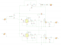
Revised:
1703012834294.png
 

Attachments

Irving

Joined Jan 30, 2016
5,195
The datasheet for SSM2167 shows a capacitor on the GND line so that's why I put it there. Not sure what the reason behind it is. should i still remove it?
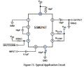
No it doesn't - you're misreading the datasheet though I'll give you its badly drawn... Pin 1 top left... the pin at the bottom is pin 6 AVG which you have on your drawing too...

1703013101901.png

Just to clarify this is NOT going in an aircraft. It is for my UTV a Can-am Maverick. If something fails it is 100% not critical. If I had the money for a plane I'd be able to buy the commercial thing!
All the more reason for the filtering - automotive can be worse than planes...

Ohhh, I like that... :):):)

1703013535327.png
 

Thread Starter

eyeTech

Joined Dec 12, 2023
11
No it doesn't - you're misreading the datasheet though I'll give you its badly drawn... Pin 1 top left... the pin at the bottom is pin 6 AVG which you have on your drawing too...

View attachment 310364


All the more reason for the filtering - automotive can be worse than planes...

Ohhh, I like that... :):):)

View attachment 310366

Ohh I see where I went wrong. Ok, I removed them.

do you have any suggestions as to the values of the capacitors and inductor?

Yes, its a fun machine. Just too loud, hence the intercom lol
 

Thread Starter

eyeTech

Joined Dec 12, 2023
11
That helps a lot.

Just to clarify, is there any kind of PTT switching in the vehicle now? If not, is that why you want a voice/noise gate circuit?

ak

There is no PTT, it is just an open duplex intercom between the 2 passengers. I figured the noise gate could help cut out extra noise that isn't speech. There's a good chance that it stays open all the time.
 

MisterBill2

Joined Jan 23, 2018
28,090
OK, thanks for the vehicle type clarification. I am aware of intercoms in noisy aircraft, not in ORVs. Always needed, (usually) in choppers, And on some motorcycles.
 

AnalogKid

Joined Aug 1, 2013
12,241
Add a coupling capacitor in series with R9. Otherwise, a small amount of DC on the Bluetooth device output could saturate the audio power amplifiers.

Also, you have one 386 powered by 5 V and one powered by 12 V. I recommend 12 V for both.

And - Consider using ebay modules for both the SSM2167's and the LM386's. If you desolder the mic element and replace it with a 2-pin header, The audio processing becomes a plug-in component for less than the price of the components; same for the power amps. The circuit board handles physical mounting, I/O and interconnections, the summing components, and the power system. All through-hole components, easy to assemble and maintain. I get that you would lose the audio compression and gate adjustments, so the question is how much effort is it worth to have those controls?

ak
 
Last edited:

Irving

Joined Jan 30, 2016
5,195
OK, thanks for the vehicle type clarification. I am aware of intercoms in noisy aircraft, not in ORVs. Always needed, (usually) in choppers, And on some motorcycles.
On the subject of noise, albeit electrical rather than acoustic, in a past life many moons ago I had more than my fair share of designing, developing & approval testing of audio/radio equipment in vehicles ranging from an army Land Rover, fast patrol boats, jet fighters and a supersonic bomber - all of which had their own quirks in terms of EMI ingress, outgoing radiation (keeping them electromagnetically 'quiet'), etc. But a common theme was, whatever the supply voltage from 12v - 48v, it was intrinsically noisy and needed serious filtering.
 

AnalogKid

Joined Aug 1, 2013
12,241
Agree. We found ground-mobile to be the worst, followed by naval. Airborne never gave us much grief; the specs were way worse than the actual platforms.

OTOH, I did some work, including an intercom, for an ambulance company. Now there was some baaaad power.

MCM Electronics (now a part of Newark) used to have a selection of chokes for automotive power filtering.
https://www.newark.com/mcm-partnership

TS: Where are you located?

ak
 

MisterBill2

Joined Jan 23, 2018
28,090
For use in an engine driven application like this, with a 12 volt supply system, the polarized capacitors should be rated at least 25 volts. The power is probably from a battery charge connection on the engine magneto, and probably the DC has noise spikes that contain power.
 

Irving

Joined Jan 30, 2016
5,195
The post from @LeckieBrent is a direct output from chatGPT... this could be a spambot... I've seen similar on forums I moderate. Superficially useful but out of context with where the thread is going... reported to mods for checking...


ChatGPT 3.5

What types of capacitors should i use in my project for this list : The list of caps are: 470nF - 1 100nF - 3 470nF - 1 1.5nF - 1 100uF 16v - 2 10uF 16v - 4 22uF 16v 1 220uF 16v - 1

Choosing capacitors for a project involves considering various factors like capacitance value, voltage rating, size, and specific application requirements. Based on the provided list of capacitors you have, here are some guidelines on their potential uses:
  1. 470nF - 1: This capacitor is suitable for decoupling, filtering, and timing applications. It's a common value for various electronic circuits, particularly in filtering out noise or in timing circuits.
  2. 100nF - 3: Similar to the 470nF capacitor, these are often used in decoupling applications and filtering high-frequency noise in circuits. They are also good for bypass capacitors in power supplies.
  3. 1.5nF - 1: This capacitor is a smaller value and might be used in precision timing applications, filtering very high frequencies, or for coupling in specific circuits that demand low capacitance.
  4. 100uF 16V - 2: These capacitors are electrolytic capacitors, suitable for applications like power supply filtering or energy storage due to their relatively high capacitance. They are polarized, so be cautious about their orientation when used in a circuit.
  5. 10uF 16V - 4: Similar to the 100uF capacitors but with lower capacitance. They are also electrolytic and might be used in various applications including signal coupling, filtering, or bypassing.
  6. 22uF 16V - 1: Another electrolytic capacitor with a slightly lower capacitance value. It can be used in similar applications as the 10uF and 100uF capacitors, depending on the specific requirements of your project.
  7. 220uF 16V - 1: This capacitor has a higher capacitance compared to the others and can be useful in applications where higher energy storage or filtering is required in the circuit.
For any specific application or circuit, the choice of capacitors from this list will depend on the voltage requirements, desired capacitance, and whether the application requires polarized (electrolytic) or non-polarized capacitors.
Always ensure that the voltage rating of the capacitor is higher than the maximum voltage expected in your circuit to prevent damage to the components. Also, consider the tolerance of the capacitor values as it might influence precision-based circuits.

[EDIT @ 16:17 GMT] - post removed by mods
 
Last edited:
Top