 Facebook
 Google
 GitHub
 Linkedin
Hi,
I am using following,
Crimping Tool:
Pro's Kit 608-384
Crimp Shells:
1) Molex Pico-Lock Crimp Terminal (28AWG to 24AWG)
2) Molex MicroBlade (30AWG to 24AWG)
Wire Size:
1) 26 AWG
2) 28 AWG
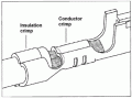
I tried to crimp all the possible combinations but each time the insulation crimp got more flattened so that crimp terminal could not get into its housing. And When I try to make the insulation crimp round enough to get into the housing (Using plier from sideways), it loses its grip on the insulation.
Can anyone suggest me where am I going wrong or what are the alternatives or the tips I can try (I don't want to spend money on Molex Crimping tool which is very expensive).
Thanks.
Following are the links for:
Crimping Tool:
Pro's Kit 608-384
https://vikiwat.com/en/crimping-pliers-608-384-pro-s-kit.html
Crimp Shells:
1) Molex Pico-Lock Crimp Terminal (28AWG to 24AWG)
http://uk.rs-online.com/web/p/pcb-c...3743D37383938333738267374613D3738393833373826
2) Molex MicroBlade (30AWG to 24AWG)
http://uk.rs-online.com/web/p/pcb-c...3743D36373036343038267374613D3637303634303826
I am using following,
Crimping Tool:
Pro's Kit 608-384
Crimp Shells:
1) Molex Pico-Lock Crimp Terminal (28AWG to 24AWG)
2) Molex MicroBlade (30AWG to 24AWG)
Wire Size:
1) 26 AWG
2) 28 AWG
I tried to crimp all the possible combinations but each time the insulation crimp got more flattened so that crimp terminal could not get into its housing. And When I try to make the insulation crimp round enough to get into the housing (Using plier from sideways), it loses its grip on the insulation.
Can anyone suggest me where am I going wrong or what are the alternatives or the tips I can try (I don't want to spend money on Molex Crimping tool which is very expensive).
Thanks.
Following are the links for:
Crimping Tool:
Pro's Kit 608-384
https://vikiwat.com/en/crimping-pliers-608-384-pro-s-kit.html
Crimp Shells:
1) Molex Pico-Lock Crimp Terminal (28AWG to 24AWG)
http://uk.rs-online.com/web/p/pcb-c...3743D37383938333738267374613D3738393833373826
2) Molex MicroBlade (30AWG to 24AWG)
http://uk.rs-online.com/web/p/pcb-c...3743D36373036343038267374613D3637303634303826
Attachments
-
 7.1 KB Views: 6


