Sample device for insulation resistance test

Thread Starter

ara_S5

Joined Sep 28, 2024
3
Hello everyone!

I am trying to build a sample device which needs to have inside a >21gigaohm and it has to pass a test, an insulation resistance tester applies 1000V DC and then it shows the resultant resistance.
I already build one but unfortunately it didn't work.
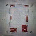
I connected in series 10G + 10G + 2G on a PCB, I couldn't find greater resistance values, that's why I make this arrangement.
When I performed the test it gave 13Gigaohms sometimes even 8, maybe is the solder or the pcb material.
Do you have any ideas about how can I achieve >21G or sugestions about the materials? It has to be constant and reliable, I was thinking about simulating the resistance with transistors or OPAMP.
 

MisterBill2

Joined Jan 23, 2018
27,311
It may be that your tester is correct, but that the actual resistance IS much lower. Did you measure the resistance between those two connections before adding the resistors?? PC board material is far from a perfect insulator.
Years ago, Bob Pease wrote a series of articles about high resistance, and related concerns. If you can find those and read them you will learn a great deal.
 

MisterBill2

Joined Jan 23, 2018
27,311
In most instances, the resistance of materials chosen to be insulators is great enough to not be of consequence. That means that for most applications, any resistance greater than ten megohms is "good enough." So mostly the much higher, but far from infinite resistance values are not a problem and most of us can ignore them.

BUT CERTAINLY, "most" is not the same as "ALL."
 

michael8

Joined Jan 11, 2015
472
Check the voltage rating of those resistors. Most aren't rated anywhere close to 1000V. Usually the solution
for high voltages is many resistors in series and extra spacing.
 

panic mode

Joined Oct 10, 2011
4,927
what are the exact resistors that you use (product part numbers) and what is the exact construction method?
if you want dummy load for insulation tester, three resistors are not going to cut it. also form factor matters. having three SMD resistors in series is certain to fail. like all components, resistors only behave in predictable way within certain parameters. high voltage is always a challenge.

say you have 0.1Watt 10 GOhm resistor... using simple P=V^2/R gives V=SQRT(P*R) = 31.6kV
should be plenty, right? actually no...

at high voltages you need larger distances... just take a look at fuse designs and notice that fuses for higher voltage are much longer. also PCB is not that good of an insulator. which is why slots are used to limit creepage current even at much lower voltages (100V or so).

as previous posts suggest, the usual solution is to use many resistors in series to get that extra spacing....
1727789667148.png


... I was thinking about simulating the resistance with transistors or OPAMP.
wrong idea... transistors and OpAmps have tiny structures. to deal with high voltage you need large structures. this is why power lines and switchgears are so large.

an example of resistors for high voltage:
https://www.ohmite.com/assets/docs/res_rx1m.pdf
https://www.vishay.com/docs/68001/fhv-radial.pdf
 
Last edited:

Thread Starter

ara_S5

Joined Sep 28, 2024
3

Attachments

MisterBill2

Joined Jan 23, 2018
27,311
One interesting experiment will be to do a test on the sample without any resistors installed. See what the fixture resistance is. That will avoid the problem of the resistors not being adequate for the voltage applied. AND it will reveal any leakage currents.
 
Top