Instrumentation Amplifier Bandwidth Question

Thread Starter

Electro Kid

Joined Apr 23, 2017
18
So I have a new project which I am currently working on which needs some protection...

I need to build an OCP which triggers at around 100A.
My shunt resistor is 300µΩ and thus the voltage to trigger on is 30mV.

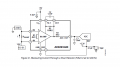
I just came across the AD8293G80 which is an amplifier with a fixed gain of 80.
This device would give me 2.4V which I would then feed into a comparator to trigger at the 100A mark.

I think I am missunderstanding the datasheet...
The datasheet states that the slew rate and the bandwidth is filter limited.
I need to check the current status at a rate of 30-40KHz.
Can this device reliably sample at that rate with low noise and high ripple rejection?
How am I supposed to know what the max bandwith is? Can I just assume that the clock rate of 60KHz is the max?
Also I can't seem to find what the propagation delay of this device is.

Can I connect one of the Inputs to the ground without having to worry about more noise?
The shunt resistor will have the same ground potential as the amp.

Any help apriciated!
Thanks in advance and best regards from Germany!!!
 

ronsimpson

Joined Oct 7, 2019
2,986
For some reason I can not find out how fast the amplifier is with out a filter. I see the part is completely trash at 60khz. Here is a graph with the filter set to 10khz.
1622204375839.png
If you are looking at the current in a load (motor current) then 10khz is more than fast. If you are looking at a MOSFET switching at 100khz (square wave or ramp) then this is too slow. You will get a average of many cycles but you will not see a peak.

More information please.
 

Thread Starter

Electro Kid

Joined Apr 23, 2017
18
It is a MOSFET switching at frequency's from 20 to 40Khz Square wave with an 8Bit PWM from 0 to 100%.
The load is an inductor.

What about the propagation delay, any idea what I can expect?

Thanks.
 
Last edited:

Thread Starter

Electro Kid

Joined Apr 23, 2017
18
Hi, ericgibbs,

I am trying to keep the coast down as much as possible.
A 14$ chip would be by far the most expensive device in my design...
 

ericgibbs

Joined Jan 29, 2010
18,766
hi
I have tried various options on the simulation model, I cannot get it work as I would expect.

The response specification for higher frequencies is limited,

Checking their typical circuit in the datasheet shows the Load in the low side to 0V common.???

Check this link.
https://ez.analog.com/amplifiers/in.../f/q-a/16526/ad8293g160-spice-model-bandwidth

Clip:
As for the bandwidth of 500kHz, I think this is a typo error. It should be 500Hz based on the typical value of the datasheet. This bandwidth is filter limited and so as you change the filter, the bandwidth also changes (please refer to figure 4 and 7 of the datasheet). Also, take note that the higher the bandwidth, the higher the noise (shown in Figure 11 of the datasheet).
E
 

Attachments

ronsimpson

Joined Oct 7, 2019
2,986
If you wanted a more normal op-amp you need a "40mhz" part to have any gain at high frequencies.
Many parts will not like running at ground.
With a 30mV signal a input offset voltage of 3mV will look large.
Do you have a negative supply voltage anywhere?
 

Thread Starter

Electro Kid

Joined Apr 23, 2017
18
I dont have a negative supply voltage nor the space for that on the pcb anymore.
The voltage offset etc is the reason why I didn't go with a normal opAmp in the first place.

Is there any other option?
All available voltages share the same ground as well as the device to be measured.
I have 3.3V, 5V, 12V and 48V I can play around with. The 5V rail has the lowest ripple and noise.

How do I know which parts do not 'like' to be on ground?
 

ronsimpson

Joined Oct 7, 2019
2,986
Most amplifiers have "input common mode range". Which is the voltage at witch the inputs function.
It is common for the inputs to need to be 1.5 volts below the plus supply. Some types of amplifiers will work to 0.6 volts below the bottom supply. "R-R" amplifiers will work from supply to supply. The rest will not work over that wide a range. "Audio" amplifiers are designed to work neat the center of the two supplies and the input will not work near either supply. Each type of amplifier has different numbers to watch out.
 

Thread Starter

Electro Kid

Joined Apr 23, 2017
18
Thanks for all your help I really appreciate it.

I was browsing a little on mouser and found the INA301A3.
It seems like this chip does all I need, it even has an integrated comparator.
The only issue I can see at the moment with this device is that it is a big VSSOP package.
Other than that I think I would be fine with it.
Could you double check, not that I am missing something her...

I just came across the INA381A3 and I am wondering if that is an option as well?
It is not as accurate as the INA301, but it comes in a WSON package which is a little easier to place on the board.

Thanks in advance!
 
Last edited:
Top