The peaking is likely an artifact of how SPICE calculates the initial starting conditions.
Here is my sim using the startup option which ramps up the supply voltages:
I also had to modify my SPICE settings as shown below to get it to simulate in a reasonable time.
With no emitter resistors Q1 and Q2 have a lot of voltage gain in the loop. I would add emitter resistors to both such that the conversion of Q1 base voltage to Q2 collector current is much more predictable and linear. As needed add loop gain by adding gain to U2 via boosting R4. I'm also wondering if a series RC from Q2 collector to U2 - input might also help kill oscillation.
Quite a constant current regulator circuit for the PT100 sensor. Of course there will be a spike until the capacitors charge up in the PT100 current supply.
I am attaching the simulation file of one of my circuit.It consists of many opamps and BJT's. I know how to check the stability of this circuit(I know it for single opamp circuits).
My input is V3(I_PT100_SET) and output is I_PT100_ACT .
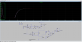
Below is the output waveform.I can see some ringing initially.Can you please help me to compensate it.
With no emitter resistors Q1 and Q2 have a lot of voltage gain in the loop. I would add emitter resistors to both such that the conversion of Q1 base voltage to Q2 collector current is much more predictable and linear. As needed add loop gain by adding gain to U2 via boosting R4. I'm also wondering if a series RC from Q2 collector to U2 - input might also help kill oscillation.
Until the capacitors charge to a stable voltage the circuit will not be in the stable conditions. Designing to avoid startup transients is often a challenge. Just exactly WHAT is C1 (22nF) doing for you?? That is undoubtedly the source of your spike, aside from the effects of assorted stray couplings.
Until the capacitors charge to a stable voltage the circuit will not be in the stable conditions. Designing to avoid startup transients is often a challenge. Just exactly WHAT is C1 (22nF) doing for you?? That is undoubtedly the source of your spike, aside from the effects of assorted stray couplings.
 Facebook
 Google
 GitHub
 Linkedin