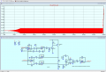
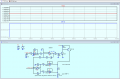
LIKE I STATED: Until a capacitor charges to the level that is present in stable operation, the circuit is not functioning in the intended steady state. Thus there could be a spike until the cap charges.
In ADDITION, if the purpose is to accurately measure temperature, that is simply not possible with the arrangement shown in post #23. The same connections used to supply the current are also used to measure the voltage developed across R14, wich I am guessing to be the 100 ohm Pt RTD device. It might possibly work in a simulation, but not in a real world where every connection has some resistance.
THERE IS a sound reason for always utilizing a KELVIN connection scheme along with a Pt RTD sensor resistor.
hi hoy,
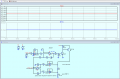
The reason your circuit output shows oscillations is that the ADA4077 is unstable when the gain of the OPA is set to less than unity.
It is currently set for approx -0.5
Thanks Eric.
I don't have much idea where it is used.Given me for simulation.One thing I know is the current needs to flow through R13 is 20mA
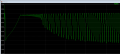
May I know the role of R5 and R6 (other than Biasing).I changed the value of R5 and R6 to 100K the waveform is as shown below.
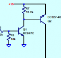
Without emitter resistors Q1 and Q2 provide a significant current gain which, given the R5 base resistor and R13+R22 collector load result in a high voltage gain. R5 value gives Vin to I base, Q1 Hfe gives Ib1 to Ic1 gain, Q2 Hfe gives Ib2 to Ic2 gain, and R13+R22 combined gives Ic2 to Vout. Due to Hfe variations and change with temperature and current it is often best to add an emitter resistor to provide a more predictable Vin to Ic transfer function. For Q2 a lower value of R7 would also help reduce the current gain of that stage.
Overarching concern is that if your control loop has gain of (or greater than) unity at the point where the negative feedback delay approaches 180 degrees of phase the circuit will oscillate. Having predictable gains in a circuit is critical to preventing the likelihood of oscillation occurring. Emitter resistors help with having predictable, stable gains.
In addition to that detailed explanation, having excess gain, along with, and sometimes causing, excessive phase shift, provides the elements required for oscillation, or at least instability. There are situations where excess is OK, and in amplifiers that is not one of those.
The spike certainly looks like an RC time constant shape. "Peaking" usually refers to a frequency response variation. Discovering if that is the source will be as simple as changing the capacitance value and running the simulation again.

 Facebook
 Google
 GitHub
 Linkedin