 Facebook
 Google
 GitHub
 Linkedin
Hello
I am a novice hobbyist and need some help with interpretation of what I see on my pocket size FNIRSI oscilloscope.
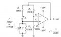
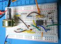
Setting the triggering point on this cheap scope is not easy and not very good. I rely on an Auto setting mostly otherwise its a handy gadget for audio frequency playing around. I built a Wein oscillator on breadboard and used a 100K ganged pot in place of the two 100k resistors in the circuit design attached.
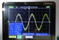
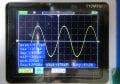
I obtained stable oscillation as I varied the pot from about 5KHz to 20KHz but the display on the scope was really messy (noisy). Normally I don't see this level of what I am calling noise but I need help on interpreting what the cause of the noise is. The funny thing is that if I switch the power off the oscillation remain for a few seconds and the trace is very clean just like you would want with the power on.
Is the "noise" I see with power on just due to poor triggering on the scope? I was not using an supressing capacitors on the power supply rails but the power supply has a low ripple and normally this has not been a problem. Since I am only interested in low frequencies I used a 741 op amp. I attached scope trace with the power on and then with the power off.
Thanks for any help
I am a novice hobbyist and need some help with interpretation of what I see on my pocket size FNIRSI oscilloscope.
Setting the triggering point on this cheap scope is not easy and not very good. I rely on an Auto setting mostly otherwise its a handy gadget for audio frequency playing around. I built a Wein oscillator on breadboard and used a 100K ganged pot in place of the two 100k resistors in the circuit design attached.
I obtained stable oscillation as I varied the pot from about 5KHz to 20KHz but the display on the scope was really messy (noisy). Normally I don't see this level of what I am calling noise but I need help on interpreting what the cause of the noise is. The funny thing is that if I switch the power off the oscillation remain for a few seconds and the trace is very clean just like you would want with the power on.
Is the "noise" I see with power on just due to poor triggering on the scope? I was not using an supressing capacitors on the power supply rails but the power supply has a low ripple and normally this has not been a problem. Since I am only interested in low frequencies I used a 741 op amp. I attached scope trace with the power on and then with the power off.
Thanks for any help
Attachments
-
 23.5 KB Views: 50
 -
 2.2 MB Views: 45
 -
 2.1 MB Views: 43
Last edited by a moderator:


