Facebook
 Google
 GitHub
 Linkedin
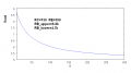
The single resistor biasing scheme is essentially driving the base with a current source, and the collector current varies with beta.
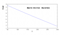
A stiff voltage divider biases it with a voltage source and the collector current rises to the level at which the emitter resistor drop is roughly 0.6V less than the base voltage. This does not depend strongly on beta.
It is obvious to me which is preferred.
A stiff voltage divider biases it with a voltage source and the collector current rises to the level at which the emitter resistor drop is roughly 0.6V less than the base voltage. This does not depend strongly on beta.
It is obvious to me which is preferred.