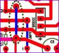
I built another unit today. The problem I am having now is the timing works correctly but after the time delay the motor starts again in the same direction. Below is a layout for the latest prototype.
I built another unit today. The problem I am having now is the timing works correctly but after the time delay the motor starts again in the same direction. Below is a layout for the latest prototype.
Check that you have not mixed up the SW1 and SW2 limit switch connections. If that don't work, monitor the voltage of pin#1 of 4013 to see if it changes when you press either limit switch. If there is no changes, 4013 is bad.
If the voltage on pin#1 changes, then you have a bad 2N7001 or bad relay.
I had already removed both relays. I installed new relays this AM. Still no luck. I removed and replaced 4013, no change. Replaced both 2N7000's. Plugged unit in and it started out working fine. After 3-4 reversal ops the switches again have no effect on the ckt. At this point I took voltage measurements. 0v @ both pin 4 and 6 of 4013, 3.5v @ Q4 gate.
I then measured the voltage @ pin 1 of 4013. Motor runs as soon as plugged in. 15v @ pin 1. Press sw 2, voltage @ p1 goes to 0v motor still turning. Press sw1, voltage goes to 15v motor still turning.
After 3-4 reversal ops the switches again have no effect on the ckt. At this point I took voltage measurements. 0v @ both pin 4 and 6 of 4013, 3.5v @ Q4 gate.
Your Q4 is defective. Therefore it cannot trigger the 555 to stop the motor. CD4013 is responsible for changing direction of motor rotation and not for stopping the motor.
If pressing the limit switch motor does not change direction then it is likely that both 2N7000 are damaged or defective.
What I don't understand is why. Q4 2N7000 has a continuous gate voltage rating of ±20V and surge of ±40V, source current 200mA cont. and 500mA pulsed. It is comfortable in driving a relay fitted with an back emf protection diode.
Measure and post back the relay coil resistance and check the diode across the relay coil is fitted in correct polarity.
The cathode of D3 on relay one is attached to pin #3 of 555, the anode to -vc. The cathode of D4 on relay 2 is attached to +vcc, the anode to drain of Q1. The resistance of the relay coil is 360 ohms. I measured the relay coils both w/ and wo power. Power on relay 1 = 27ohms, r2 = open.
Power off r1 & r2 = 370 ohms. I also measured voltages to the following:
4013 p14=14.7v, p1=14.7v,q1 gate=3.7v, p4=.03, p6=0.0v.
One only measures component resistance with power off. With power on, you risk damage the component, getting incorrect value or damage the meter. The 370Ω coil resistance of the relay is ok. They draw only 40mA at 15V so no problem there for the 2N7000.
Diode direction is also OK if by cathode, you meant the direction that the diodes points to. e.g. like this. anode --|>|---cathode
Q1 gate should be over 12V if CD4013 Pin#1 is at 14.7V and zero volt if pin#1 is at 0V.
This indicates that 2N7000 is defective. This is now the second or third case of damaged/defective 2N7000 found. Where are these 2N7000 from?
Yes, by cathode I am referring to the banded end of the diode. As to the 2N7000 I purchased them through an EBay store in Asia. I won't do that again. I purchased new units from Allied Electronics, a large US distributor.
I will wait for them before assembling another board.
Is it possible that something in the board design could be causing the mosfets to fail, or just a bad batch? I have been very careful to avoid the leads and handle by the top only. I also moved some components around to make the board layout a little neater. If you can briefly review the layout for correctness I would appreciated it.
Thank you.
It seems that each time I put a board together I have some type of problem. Could you explain the operation of circuit as to how these components interact. My elementary understanding of how the board works is as follows.
When ac is applied to board the 555 begins delay during which time R1 is energized, opening the AC connection to R2. After time delay R1 coil is de-energized allowing power from R1 to com/nc connection of R2. This nc contact is to red motor lead. The motor runs until sw2 is closed at which time R1 coil is energized, stopping motor and 555 starts time delay again. Pin 1 of 4013 then energizes R2 coil, I assume, using 2N7000 as a switch. This diverts ac to black motor lead. After time delay R1 de-energizes allowing ac through R2 to black motor lead.
Are there specific voltage tests I can do to verify each component to be operating correctly? Perhaps I can better diagnose problems rather than to bother you every day.
Yes, by cathode I am referring to the banded end of the diode. As to the 2N7000 I purchased them through an EBay store in Asia. I won't do that again. I purchased new units from Allied Electronics, a large US distributor.
I will wait for them before assembling another board.
That could be part of the reasons. One reason could be the surge or voltage peak from switching off the motor getting back into the low voltage circuit. This can be eased by fitting a resistor+capacitor snubber across the relay contact.
Another possible reason is the high circuit voltage of 15V. This is close to the maximum working voltage of 18V for both CD4013B and 555. The best voltage is 12V and since you don't have a voltage regulator on the PCB, a transformer secondary of 9V or 8V would be the best choice.
If you are already using a 9V one then the transformer is actually outputting 10V instead.
You could also consider using a 6V secondary transformer and changing both relays to one with a 6V operating coil. Other circuit component can remains unchange. This could be another good option.
If you want to make a lot of these and sell them, there are other considerations possible to make the circuit more robust but would increase the production cost.
Your new PCB design is fine. Make sure the Ground connection actually connected to the earth wire of the AC mains when using the unit.
The circuit operates in the following manner:
1. both limit switch not actuated. motor running a one direction
2. one limit switch strike the stopper, causing the 555 to trigger and energise relay R1, cutting off power to motor. Also the CD4013 output pin#1 changes simultaneously. After a short delay, determine by resistor 330K and capacitor 0.1uF, this change reaches relay R2 via 2N7000 and relay R2 either energises or de-energises to cause a change of motor connection. Notice that this should happen after the motor power has been cut off via R1. May be this time is too short in the original design. You can double this timing by using a 1MΩ resistor instead of 330K or using a 0.22uF capacitor instead.
3. after the motor connection change, there is still no power to the motor because power is still cut off by relay R1, until finally 555 times out and relay R1 de-energise, providing power again to the motor circuit via its NC contact.
4. because of the motor connection changes earlier in (2.) above, motor will now runs in opposite direction and ultimately striking another limit switch and the same sequence of event occurs again.
The transformers I purchased are rated @ 10v. The actual secondary voltage is 12v. Could you offer a few options, perhaps from most to least expensive, to make the board more reliable? This device would typically be working 12 hours a day 7 days a week so a robust design would be an important consideration. I would like to use the 10v tx and 12v relays initially. I purchased 12 tx and 24 relays for better pricing and shipping costs. If these would be the only major changes in the circuit aside from perhaps capacitor and/or resistor value changes I will order the lower voltage components for future units. If you could incorporate these mods into your original schematic I would appreciate it.
Thanks, Joe
This is how the motor and controller are suspended from the rail. To put these in perspective, the control board enclosure is ~5"h x 3"w x 1.6"d. I would like to maintain a board size of 3" x 4" as this will give me no waste when cutting from larger 12x12 or 12x18 ptoto board. This size also allows for a good fit within the enclosure. The motor is quite small measuring 2-1/4"w x 2-1/4"h x 2-1/4"d. The photo also shows the rail, and the eye bolt from which the lamp is suspended.
I don't have a completed unit yet so this was downloaded from net. If you rt. click thumbnail and save as jpg you will be able to increase the size through Windows picture and fax viewer. The photo is an end on view of the assembly. The rail is "T" shaped. The motor is on LHS the controller on RHS. The drive wheel is between the two. The limit switches would be one on each side of controller box. I hope this helps.
Looking at the photo it appears there is a flat bar going through the top l&r sides of the board enclosure. The limit sw plunger and contacts are mounted internally and the flat bar hits the stops at either end of the track actuating the switch. The small round device visible in the center of the left side of the enclosure is for external potentiometer adjustment. Only the 4 motor leads are bridged across the trolley, all other components are inside the enclosure.
I meant to ask you why does the motor use such a large capacitor? It is rated .68uF @ 400v. Is there another value I could use to save on space and cost?
 Facebook
 Google
 GitHub
 Linkedin
 22.3 KB Views: 26


