Facebook
 Google
 GitHub
 Linkedin
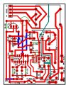
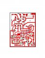
Q4 was the problem. I had confirmed the values of all resistors prior to installing them. As soon as I removed Q4 the gate voltage went to 0V. I installed a new Q4 and all is good. How sensitive are they to heat? should I use a heat sink when soldering them?
inexpensive timing relay circuit
- Thread starter strpdbas
- Start date
")