Inductor selection

SgtWookie

Joined Jul 17, 2007
22,230
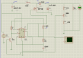
Re-draw and re-post your schematic with the actual values/part numbers you are using shown on it.

The schematic you posted earlier apparently does not represent what you have now.

Using the values on the schematic that I can read and the other values you've supplied, I see the initial output voltage climbing immediately to 80v.
C1 is too large at 15nH.
L1 is much too large at 3mH.
 

SgtWookie

Joined Jul 17, 2007
22,230
You need to re-post your schematic that represents the circuit that you have now.

C1 should be 1nF or 2nF.

L1 is much too large.
 

SgtWookie

Joined Jul 17, 2007
22,230
Decrease R1 to 3k. This lowers the maximum PWM percent of the MOSFET, which then operates the inductor in discontinuous mode.

Decrease C1 to 5nF or somewhat less. Your frequency is currently so low with such a high duty cycle that your inductor is saturating.

Increase C5 to 10uF or greater.
 

Thread Starter

xw0927

Joined Dec 19, 2010
114
Decrease R1 to 3k. This lowers the maximum PWM percent of the MOSFET, which then operates the inductor in discontinuous mode.

Decrease C1 to 5nF or somewhat less. Your frequency is currently so low with such a high duty cycle that your inductor is saturating.

Increase C5 to 10uF or greater.
So you mean I got to change my boost converter operation mode into discontinous mode? But is that okay for my circuit design?

Thanks for your advice, I will try to decrease the duty-cycle and make the frequency higher :)
 

SgtWookie

Joined Jul 17, 2007
22,230
What's happening is that your frequency is so low and your duty cycle is so high, that you wind up with around 10A current flowing through your inductor. No wonder it's getting hot and sizzling.

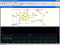
Have a look at the attached. With the changes I've suggested, current through the inductor will be limited to around 1.3A. The value for C1 should be in the range of 1nF to 5nF.

Basically, the smaller C1 is (increasing the frequency), the smaller the value inductance that you could use for L1 - within the limits of the 555 timer. I wouldn't go much over 50kHz or you'll start getting into problems with parasitics, particularly on a breadboard.

You should use a resistor between the 555 pin 3 and the MOSFET gate; I'll suggest 10 to 43 Ohms. Without a resistor there, the MOSFET gate will "ring", turning it on and off very rapidly, and generating heat.
 

Attachments

Thread Starter

xw0927

Joined Dec 19, 2010
114
What's happening is that your frequency is so low and your duty cycle is so high, that you wind up with around 10A current flowing through your inductor. No wonder it's getting hot and sizzling.

Have a look at the attached. With the changes I've suggested, current through the inductor will be limited to around 1.3A. The value for C1 should be in the range of 1nF to 5nF.

Basically, the smaller C1 is (increasing the frequency), the smaller the value inductance that you could use for L1 - within the limits of the 555 timer. I wouldn't go much over 50kHz or you'll start getting into problems with parasitics, particularly on a breadboard.

You should use a resistor between the 555 pin 3 and the MOSFET gate; I'll suggest 10 to 43 Ohms. Without a resistor there, the MOSFET gate will "ring", turning it on and off very rapidly, and generating heat.
Really Thanks a lot!!! I will try this out when I got the component. Thanks a lot!
 

Thread Starter

xw0927

Joined Dec 19, 2010
114
What's happening is that your frequency is so low and your duty cycle is so high, that you wind up with around 10A current flowing through your inductor. No wonder it's getting hot and sizzling.

Have a look at the attached. With the changes I've suggested, current through the inductor will be limited to around 1.3A. The value for C1 should be in the range of 1nF to 5nF.

Basically, the smaller C1 is (increasing the frequency), the smaller the value inductance that you could use for L1 - within the limits of the 555 timer. I wouldn't go much over 50kHz or you'll start getting into problems with parasitics, particularly on a breadboard.

You should use a resistor between the 555 pin 3 and the MOSFET gate; I'll suggest 10 to 43 Ohms. Without a resistor there, the MOSFET gate will "ring", turning it on and off very rapidly, and generating heat.
Sorry for my ignorance. May I know what is the meaning that you said :the MOSFET gate will "ring"?
And is that R6 in my circuit is not necessary ? Thanks again.
 

SgtWookie

Joined Jul 17, 2007
22,230
Sorry for my ignorance. May I know what is the meaning that you said :the MOSFET gate will "ring"?
And is that R6 in my circuit is not necessary ? Thanks again.
It's hard to explain, because it's hard to understand.

Even short wires have inductance. Inductors don't like changes of current, and try to keep the current flowing at the rate it was; sort of like inertia.

Please just trust me on this. Use a resistor of around 22 Ohms from the 555 pin 3 to the MOSFET gate. It will cause the gate ringing to cease very quickly.
 

Thread Starter

xw0927

Joined Dec 19, 2010
114
It's hard to explain, because it's hard to understand.

Even short wires have inductance. Inductors don't like changes of current, and try to keep the current flowing at the rate it was; sort of like inertia.

Please just trust me on this. Use a resistor of around 22 Ohms from the 555 pin 3 to the MOSFET gate. It will cause the gate ringing to cease very quickly.
Oic, I tried to search something about that also, it's really very confusing.

Of course I trust on you, you do help me a lot...
 

Thread Starter

xw0927

Joined Dec 19, 2010
114
@Sgtwookie

I have connected the circuit as you described last time, by changing the R1 and C1 to 3kOhms and 2.2nF.

However, when i connect the circuit in this way, the output is not changeable which means when I alter my Pot, the output remains the same. ( the frequency is about 2.3Khz)

And 1 more thing that I have observed is, the output is now depending on my Inductor value.

1mH = 100V++;10mH= 51V.

I burned my 3mH inductor while I was using C1=47uF (last time, the inductor wasn't burned !!! I wonder why)

The duty cycle is about 60%.

Things that I've summarized are :
1. When switching frequency is up to 23kHz, the inductor is alright but the output is not alterable; When switching frequency is low as 1.4kHz, the output can be altered but inductor will be burst ( it's like overheat and cause the outside(cover) of the coil inductor melts.)

2. The feedback system seems like failure when frequency is as high as 20kHz. But, why?

3. For 1 &2 are the conditions under resistor as load. And, I just connected it to the real load that I wanted to connect. Things happen:
(i) The output voltage was less than just now: for 10mH, it became 30V;for 1mH, it became 80V [the output voltage is less 20V compare the just now]
(ii) When I connected to 1mH inductor, both of the inductor and Mosfet is quite hot ( i just connect it about 10++min)

4. "Hiss" sound is gone when the switching frequency is 20kHz with 60%duty cycle; "hiss" sound appears when switching frequency is 1.4kHZ... I think your assumption of saturation current of inductor is perfectly correct. :)


So, do you have any suggestion for my problem? What should I do? Thanks a lot in advanced.
 
Last edited:

SgtWookie

Joined Jul 17, 2007
22,230
Sorry it took me a while to get back to you; lots of other people want help, and I have lots of things going on myself.

This is a "work in progress" - as you were having big problems before (burning up parts), you needed to get to a point where you were within the limitations of the parts you are using.

@Sgtwookie

I have connected the circuit as you described last time, by changing the R1 and C1 to 3kOhms and 2.2nF.

However, when i connect the circuit in this way, the output is not changeable which means when I alter my Pot, the output remains the same. ( the frequency is about 2.3Khz)
Really? You should be getting around 23kHz, perhaps you mis-typed it?

And 1 more thing that I have observed is, the output is now depending on my Inductor value.

1mH = 100V++;10mH= 51V.
Are these inductors similar in physical size? Since you have not posted a datasheet for any of these inductors, I have no idea what their parameters are other than just their inductance. Physically small inductors will saturate very rapidly. Core materials vary widely in characteristics. Unless you have their complete specifications or have tested them for saturation characteristics, it'll be very difficult to determine exactly what their limit will be.
Ronald Dekker has a very helpful and informative site; I linked to it before.
Have a look at his "Flyback Converters for Dummies" page. Look at his inductor test circuit. See what the waveform on the O-scope looks like when the inductor under test saturates; the voltage across the inductor changes very rapidly. You have to avoid inductor saturation, or you will burn up parts.

I burned my 3mH inductor while I was using C1=47uF (last time, the inductor wasn't burned !!! I wonder why)
Current through the inductor became VERY high (around 10A) because it was getting saturated.

The duty cycle is about 60%.
You can increase the duty cycle by increasing R1 again.
What I would do is use a 5k or 10k potentiometer wired as a rheostat between R1 and Vcc. This will allow you to change the duty cycle while the circuit is running; however keep in mind that as the duty cycle increases, the frequency will decrease.

Things that I've summarized are :
1. When switching frequency is up to 23kHz, the inductor is alright but the output is not alterable; When switching frequency is low as 1.4kHz, the output can be altered but inductor will be burst ( it's like overheat and cause the outside(cover) of the coil inductor melts.)
OK, so you can start increasing C1 a bit to drop the frequency down, and/or increase the resistance of R1 (using a pot in series with it) to increase the duty cycle and decrease the frequency simultaneously.

2. The feedback system seems like failure when frequency is as high as 20kHz. But, why?
I have not built your exact circuit; I've simply been performing simulations using LTSpice. If you are using a breadboard with long wires running everywhere, you will have problems at higher frequencies. Long wires = lots of inductance. A 1 foot piece of wire (~300mm) will have around 0.42uH inductance. This can cause big problems with circuits that generate square wave outputs.

3. For 1 &2 are the conditions under resistor as load. And, I just connected it to the real load that I wanted to connect. Things happen:
(i) The output voltage was less than just now: for 10mH, it became 30V;for 1mH, it became 80V [the output voltage is less 20V compare the just now]
(ii) When I connected to 1mH inductor, both of the inductor and Mosfet is quite hot ( i just connect it about 10++min)
You have not mentioned what your intended load characteristics are.
In your schematic, you have 100k as a load resistor. You also have the 47k resistor/1k pot/470 Ohms to ground for the feedback which also serves as a small load.

4. "Hiss" sound is gone when the switching frequency is 20kHz with 60%duty cycle; "hiss" sound appears when switching frequency is 1.4kHZ... I think your assumption of saturation current of inductor is perfectly correct. :)
The hissing sound was likely the turns of wire on the inductor core slapping around due to the magnetic field expanding and contracting. The higher frequency causes the hiss to be at the high edge of the audible range.

So, do you have any suggestion for my problem? What should I do? Thanks a lot in advance.
What is your intended load? We need the voltage and current or VA rating or resistance.

Post a photo of your circuit as it is now.
 

Thread Starter

xw0927

Joined Dec 19, 2010
114
Sorry it took me a while to get back to you; lots of other people want help, and I have lots of things going on myself.

This is a "work in progress" - as you were having big problems before (burning up parts), you needed to get to a point where you were within the limitations of the parts you are using.


Really? You should be getting around 23kHz, perhaps you mis-typed it?
Thanks a lot for your unconditional helps and aids.

Yup, I mis-typed it... It's 23kHZ.


Are these inductors similar in physical size? Since you have not posted a datasheet for any of these inductors, I have no idea what their parameters are other than just their inductance. Physically small inductors will saturate very rapidly. Core materials vary widely in characteristics. Unless you have their complete specifications or have tested them for saturation characteristics, it'll be very difficult to determine exactly what their limit will be.
Ronald Dekker has a very helpful and informative site; I linked to it before.
Have a look at his "Flyback Converters for Dummies" page. Look at his inductor test circuit. See what the waveform on the O-scope looks like when the inductor under test saturates; the voltage across the inductor changes very rapidly. You have to avoid inductor saturation, or you will burn up parts.
I bought the inductor online, they don't provide me any datasheet. That's really bad.

Yup, they are physically in same size. The inductor test circuit is kinda of complicated. I don't really understand how to conduct that inductor test. However, I'd ordered some inductors yesterday with datasheet, hopefully, the problem could be solved. But, which part should I be paying attention to avoid saturation of inductor current? Frequency? or?


Initially, when the frequency is 1.4kHZ, feedback system works and i could adjust the output voltage from 28V to 70V. But, when the frequency is as high as 23kHz, the inductor burst. Temporary, I don't have extra inductor, so, I couldn't test whether when frequency is lower then the output can be altered or not.


However, you said that my inductor's value is quite high. But, I don't dare to connect the inductor with value lower than 1mH as I afraid that the output voltage will higher than 100V and my whole circuit will be spoilt.

But, in your opinion, should i try to put an inductor like 470uH or 100uH?


You have not mentioned what your intended load characteristics are.
In your schematic, you have 100k as a load resistor. You also have the 47k resistor/1k pot/470 Ohms to ground for the feedback which also serves as a small load.


What is your intended load? We need the voltage and current or VA rating or resistance.

Post a photo of your circuit as it is now.
[/QUOTE]

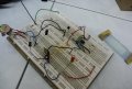
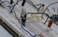
Below attachments are my circuit, my inductor(1mH or 10mH has the same physical size) and also my intended load.

My intended load is like a plastic plate with 2 copper(terminals) at both sides. It is used to provide a electric field between both sides.

When I connect my circuit to my load:

The output voltage become lesser about 20V. From 50V(when resistor as load) to 30V(intended);from 100V(when resistor as load) to 80V(intended).

For the current, when 30V, current is about 3.0++mA; when 80V, current is about 8.0++mA.

However, when i straight away connect the multimeter to the load to test the resistance, the value is in Mega Ohms... Is it this reason causing my inductor and mosfet to be HOT? Or because of the frequency?

Thanks a lot again.
 

Attachments

Last edited:

SgtWookie

Joined Jul 17, 2007
22,230
Thanks a lot for your unconditional helps and aids.

Yup, I mis-typed it... It's 23kHZ.
OK, at least the 555 frequency matches the simulation. I was wondering... ;)

Re: inductors.
I bought the inductor online, they don't provide me any datasheet. That's really bad.
Yes, it is. They may measure 1mH, 3mH, etc. at low frequency, but likely saturate very quickly when much current goes through them. All other things being equal, physically small inductors need to be operated at high frequency, or they'll get saturated quickly. However, your values of inductance are VERY large, so they need to be operated at a lower frequency. If you could get down in the range of 220uH to 470uH, your results would likely be a lot better.

You still have your 3mH inductor, right? Try removing the wire from it, carefully counting the number of complete turns around the core. From that, we can approximately calculate the number of turns of wire you'll need to wind back on it to get an inductor in a lower range.

Re: size
Yup, they are physically in same size.
They look pretty small, like around 10mm in diameter?

The inductor test circuit is kinda of complicated.
Not really - it's about the same complexity as your circuit.

I don't really understand how to conduct that inductor test.
Do you have an oscilloscope available?

However, I'd ordered some inductors yesterday with datasheet, hopefully, the problem could be solved.
What values did you order, and where are the datasheets?

But, which part should I be paying attention to avoid saturation of inductor current? Frequency? or?
It's a combination of frequency and duty cycle.
If your ON time for any given cycle is too long, the inductor will saturate, and the voltage across it will suddenly drop.
This will cause the inductor and MOSFET to heat up rapidly.

Initially, when the frequency is 1.4kHZ, feedback system works and i could adjust the output voltage from 28V to 70V. But, when the frequency is as high as 23kHz, the inductor burst. Temporary, I don't have extra inductor, so, I couldn't test whether when frequency is lower then the output can be altered or not.
You say it burst? I would have expected melting, but not bursting? Did the core shatter? Please try to better describe how the inductor failed.


However, you said that my inductor's value is quite high. But, I don't dare to connect the inductor with value lower than 1mH as I afraid that the output voltage will higher than 100V and my whole circuit will be spoilt.
The feedback circuit should pull CTRL low, which will cause the ON-time to be quite low.

But, in your opinion, should i try to put an inductor like 470uH or 100uH?
100uH would be a bit low for 23kHz. Somewhere in the range of 220uH to 470uH would likely be better.

Below attachments are my circuit, my inductor(1mH or 10mH has the same physical size) and also my intended load.
I see that you have long wires all over the place. This will cause problems.

The 555 timer connections are good; they are nice, neat, and short.
However, your MOSFET and inductor are located a LONG way away from the 555 timer. The inductance of the wiring will cause big problems.

My intended load is like a plastic plate with 2 copper(terminals) at both sides. It is used to provide a electric field between both sides.
What is this plastic plate? Some kind of electroluminescent display?

When I connect my circuit to my load:

The output voltage become lesser about 20V. From 50V(when resistor as load) to 30V(intended);from 100V(when resistor as load) to 80V(intended).

For the current, when 30V, current is about 3.0++mA; when 80V, current is about 8.0++mA.
That's what you measured through the 100k resistor? Are you sure it's not a 10k resistor? That would be correct then, as 80v/10k = 8mA. 80v/100k = 0.8mA.

However, when i straight away connect the multimeter to the load to test the resistance, the value is in Mega Ohms... Is it this reason causing my inductor and mosfet to be HOT? Or because of the frequency?
Your multimeter uses a small voltage to test for resistance. When the higher voltage output from the boost circuit is applied to the plastic plate, it might break down whatever material the plate is made from.

I don't have enough information about your plastic plate to make a good guess.
 

Thread Starter

xw0927

Joined Dec 19, 2010
114
Yes, it is. They may measure 1mH, 3mH, etc. at low frequency, but likely saturate very quickly when much current goes through them. All other things being equal, physically small inductors need to be operated at high frequency, or they'll get saturated quickly. However, your values of inductance are VERY large, so they need to be operated at a lower frequency. If you could get down in the range of 220uH to 470uH, your results would likely be a lot better.
http://malaysia.rs-online.com/web/search/searchBrowseAction.html?method=retrieveTfg&Nty=1&Ntx=mode%2bmatchallpartial&Ntk=I18NAll&Ns=stockPolicy_my|1||new_my|1&Ne=4294934505&Nr=AND%28avl%3amy%2csearchDiscon_my%3aN%29&N=4294624301+4294835590&binCount=1329&Ntt=inductor&multiselectParam=4294624301&selectSubRange=Inductors:%20Radial#breadCrumb

These are inductors I could order from another online company. I don't understand the condition of "TEST FREQUENCY". Like what you said, they might be measured under low frequency, but is there any problem regarding the test frequency?

You highlighted that my inductor value is too large, but is it a problem to use larger inductor? Would larger inductance create problem for my circuit?

And for my circuit, which type of inductor would you recommend?


You still have your 3mH inductor, right? Try removing the wire from it, carefully counting the number of complete turns around the core. From that, we can approximately calculate the number of turns of wire you'll need to wind back on it to get an inductor in a lower range.
The wire of at the inductor is too tiny(almost as small as human hair) and I failed to calculate the number of turns, but I could only say it is really a lot of turns...

Re: size

They look pretty small, like around 10mm in diameter?
Yup, it is about 10mmn in diameter, smaller than the width of a mosfet.


Do you have an oscilloscope available?
yup, I could get it in my sch lab.

What values did you order, and where are the datasheets?
http://docs-asia.electrocomponents.com/webdocs/0026/0900766b80026ad4.pdf

http://docs-asia.electrocomponents.com/webdocs/0026/0900766b80026ad4.pdf

3.3mH and 2.7mH. They are high current supression choke. And, it's expensive compare to 270uH to 470uH.:(

You say it burst? I would have expected melting, but not bursting? Did the core shatter? Please try to better describe how the inductor failed.
yaya, you're right. It was melting! Is it because of overheat due to current saturated?


I see that you have long wires all over the place. This will cause problems.

The 555 timer connections are good; they are nice, neat, and short.
However, your MOSFET and inductor are located a LONG way away from the 555 timer. The inductance of the wiring will cause big problems.
Noted. I will do a PCB board for this circuit once the testing is done :)


What is this plastic plate? Some kind of electroluminescent display?
It is just a normal glass plate(It's not plastic plate). It is something like a moulding.
That's what you measured through the 100k resistor? Are you sure it's not a 10k resistor? That would be correct then, as 80v/10k = 8mA. 80v/100k = 0.8mA.
The current measured is the current when I connected to intended load not resistor. Sorry if my sentence did mislead:p

I have change my C1 to 4.7nF.

Well, previously my output is not changeable, It's might be the problem of my BJT, it was loose. It is okay now and the output is changeable.

However, now I am still testing my circuit with 0.25watt resistor. But, the resistor is hot after a few minutes, is that normal?

The "hiss" is appearing when 0.5watt resistor is used at certain lower frequency. So, if i conclude the hiss sound is because of the switching frequency, is it correct?

And, the inductor becomes hot also, is it possible because of saturation current of my inductor?


Attachments

Last edited:

bertus

Joined Apr 5, 2008
22,953
Hello,

I think that the needed current is very low.
At the given page is stated that the current through the gel may lead to heating of the gel:

There are limits to electrophoretic techniques. Since passing current through a gel causes heating, gels may melt during electrophoresis. Electrophoresis is performed in buffer solutions to reduce pH changes due to the electric field, which is important because the charge of DNA and RNA depends on pH, but running for too long can exhaust the buffering capacity of the solution. Further, different preparations of genetic material may not migrate consistently with each other, for morphological or other reasons.
I think you do not need much power for you inverter.

Bertus
 
Top