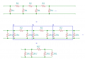
Interesting that this question should come up, given I was working on this exact problem a couple weeks ago (though with reactances rather than resistances). There's a way I know how to do it, but it's painful, and ultimately uses a lot of auxiliary variables. We can re-draw this slightly. If we have two identical resistors in parallel, then we know the equivalent resistance is half the resistance. So let's replace every instance of \(R_1\) with a set of parallel \(2R_1\). That lets us create a series of identical \(\Pi\) network elements cascaded together. In the attached picture, I have the original circuit (top), the equivalent "mid-step" circuit (middle), and the final equivalent circuit (bottom) shown.
Notice how I have each cascaded subsection boxed in and labelled 'A' - this is in reference to the transfer matrix I'm going to derive for that subsection, which I'll label as matrix \(A\). The transfer matrix is of the form:
\[
\left[ \begin {array}{c} V_{2}\\-I_{2}\end {array}
\right] =
\left[ \begin {array}{cc} \alpha_{11}&\alpha_{12}
\\ \alpha_{21}&\alpha_{11}\end {array} \right]
\left[ \begin {array}{c} V_{1}\\I_{1}\end {array}
\right]
\]
Where \(V_1\) is the voltage across the left terminals of the block, \(I_1\) is the current flowing INTO the left side of the block, \(V_2\) is the voltage across the right terminals of the block, and \(-I_2\) is the current flowing OUT OF the right side of the block. Here, we define:
\[A =
\left[ \begin {array}{cc} \alpha_{11}&\alpha_{12}
\\ \alpha_{21}&\alpha_{11}\end {array} \right]
\]
Where (if I did my math right - you may want to check!)
\[\alpha_{11} = \alpha_{22} = \frac{R_2}{2R_1} + 1 \]
\[\alpha_{12} = -R_2\]
\[\alpha_{21} = -\frac{1}{R_1}\left(\frac{R_2}{4R_1}+1\right)\]
Cascading \(N\) of these together (for the cumulative effect to get the primed values) requires a bit of matrix trickery (eigendecomposition for the simplest way I'm aware of - \(A = \mathscr{V}\Lambda\mathscr{V}^{-1}\), where \(\mathscr{V}\) is the eigenvector matrix of \(A\) and \(\Lambda\) is the diagonal eigenvector matrix of \(A\)) to get us to the following definitions for \(A' \equiv A^N = \mathscr{V}\Lambda^N\mathscr{V}^{-1}\):
\[\lambda_\pm = \alpha_{11} \pm \sqrt{\alpha_{12}\alpha_{21}}\]
\[\alpha_{11}' = \alpha_{22}' = \frac{1}{2}\left(\lambda_+^N + \lambda_-^N\right)\]
\[\alpha_{12}' = -\frac{1}{2}\sqrt{\frac{\alpha_{12}}{\alpha_{21}}}\left(\lambda_+^N - \lambda_-^N\right)\]
\[\alpha_{21}' = -\frac{1}{2}\sqrt{\frac{\alpha_{21}}{\alpha_{12}}}\left(\lambda_+^N - \lambda_-^N\right)\]
From here, we can take the primed \(\alpha\) values and reverse-engineer an effective set of \(R_1'\) and \(R_2'\) from the original definitions of the \(\alpha\) values to get us to the bottom equivalent circuit. Doing so gives us:
\[R_2' = -\alpha_{12}'\]
\[R_1' = \frac{R_2'}{2\left(\alpha_{11}'-1\right)} = -\frac{\alpha_{12}'}{2\left(\alpha_{11}'-1\right)}\]
So the total equivalent resistance becomes:
\[R_T = \left(\frac{1}{2R_1} + \frac{1}{2R_1'} + \frac{1}{R_2 + \frac{2R_1'R_1}{R_1'+R_1}}\right)^{-1}\]
I did not bother putting \(R_1'\) and \(R_2'\) in terms of \(R_1\) and \(R_2\) because the equation becomes horrifically complicated. In order to keep it "simple," it needs all the auxiliary variables.
If there IS a simpler way to do this, then I personally don't know it.
Interesting that this question should come up, given I was working on this exact problem a couple weeks ago (though with reactances rather than resistances). There's a way I know how to do it, but it's painful, and ultimately uses a lot of auxiliary variables. We can re-draw this slightly. If we have two identical resistors in parallel, then we know the equivalent resistance is half the resistance. So let's replace every instance of \(R_1\) with a set of parallel \(2R_1\). That lets us create a series of identical \(\Pi\) network elements cascaded together. In the attached picture, I have the original circuit (top), the equivalent "mid-step" circuit (middle), and the final equivalent circuit (bottom) shown. View attachment 311171
Notice how I have each cascaded subsection boxed in and labelled 'A' - this is in reference to the transfer matrix I'm going to derive for that subsection, which I'll label as matrix \(A\). The transfer matrix is of the form:
\[
\left[ \begin {array}{c} V_{2}\\-I_{2}\end {array}
\right] =
\left[ \begin {array}{cc} \alpha_{11}&\alpha_{12}
\\ \alpha_{21}&\alpha_{11}\end {array} \right]
\left[ \begin {array}{c} V_{1}\\I_{1}\end {array}
\right]
\]
Where \(V_1\) is the voltage across the left terminals of the block, \(I_1\) is the current flowing INTO the left side of the block, \(V_2\) is the voltage across the right terminals of the block, and \(-I_2\) is the current flowing OUT OF the right side of the block. Here, we define:
\[A =
\left[ \begin {array}{cc} \alpha_{11}&\alpha_{12}
\\ \alpha_{21}&\alpha_{11}\end {array} \right]
\]
Where (if I did my math right - you may want to check!)
\[\alpha_{11} = \alpha_{22} = \frac{R_2}{2R_1} + 1 \]
\[\alpha_{12} = -R_2\]
\[\alpha_{21} = -\frac{1}{R_1}\left(\frac{R_2}{4R_1}+1\right)\]
Cascading \(N\) of these together (for the cumulative effect to get the primed values) requires a bit of matrix trickery (eigendecomposition for the simplest way I'm aware of - \(A = \mathscr{V}\Lambda\mathscr{V}^{-1}\), where \(\mathscr{V}\) is the eigenvector matrix of \(A\) and \(\Lambda\) is the diagonal eigenvector matrix of \(A\)) to get us to the following definitions for \(A' \equiv A^N = \mathscr{V}\Lambda^N\mathscr{V}^{-1}\):
\[\lambda_\pm = \alpha_{11} \pm \sqrt{\alpha_{12}\alpha_{21}}\]
\[\alpha_{11}' = \alpha_{22}' = \frac{1}{2}\left(\lambda_+^N + \lambda_-^N\right)\]
\[\alpha_{12}' = -\frac{1}{2}\sqrt{\frac{\alpha_{12}}{\alpha_{21}}}\left(\lambda_+^N - \lambda_-^N\right)\]
\[\alpha_{21}' = -\frac{1}{2}\sqrt{\frac{\alpha_{21}}{\alpha_{12}}}\left(\lambda_+^N - \lambda_-^N\right)\]
From here, we can take the primed \(\alpha\) values and reverse-engineer an effective set of \(R_1'\) and \(R_2'\) from the original definitions of the \(\alpha\) values to get us to the bottom equivalent circuit. Doing so gives us:
\[R_2' = -\alpha_{12}'\]
\[R_1' = \frac{R_2'}{2\left(\alpha_{11}'-1\right)} = -\frac{\alpha_{12}'}{2\left(\alpha_{11}'-1\right)}\]
So the total equivalent resistance becomes:
\[R_T = \left(\frac{1}{2R_1} + \frac{1}{2R_1'} + \frac{1}{R_2 + \frac{2R_1'R_1}{R_1'+R_1}}\right)^{-1}\]
I did not bother putting \(R_1'\) and \(R_2'\) in terms of \(R_1\) and \(R_2\) because the equation becomes horrifically complicated. In order to keep it "simple," it needs all the auxiliary variables.
If there IS a simpler way to do this, then I personally don't know it.
You can get some bounding approximations pretty easily.
For infinite N, first pull off the left-most R1 (add it back later) and then use the trick that the resistance looking into R2 is R2 + R1||(everything to the right). Call the resistance of everything to the right Ro. Since it is infinite, Ro is also the resistance looking into R2. So you have
Ro = R2 + (R1||Ro)
This results in a quadratic with one positive real root.
Ro = R2 * (1 + sqrt(1 + 4(R1/R2))/2
Notice that if R1=R2, then the multiplier is the Golden Ratio.
You can now put Ro in parallel with R1 and you have the lowest value that your resistance can be.
This looks a lot like classwork problem for the second-semester third year engineering course, "advanced math", after all the calculus and differential equations stuff. What came close was transmission line analysis with reactance instead of resistance. I never had to deal with that in my engineering career, but I never had to design antenna arrays, either.
This looks a lot like classwork problem for the second-semester third year engineering course, "advanced math", after all the calculus and differential equations stuff. What came close was transmission line analysis with reactance instead of resistance. I never had to deal with that in my engineering career, but I never had to design antenna arrays, either.

 Facebook
 Google
 GitHub
 Linkedin