Impedance matching with only resistor

Thread Starter

Anastasios Kyriakidis

Joined Feb 5, 2019
2
Hi all,

A relatively 'silly' question but I am trying to find out why that happens and I couldn't till now.
I know of course that usually a resistor is used in series to match the impedance of the transmission line with the load.
My question is why that is always a resistor? Impedance means: resistor, capacitance, inductance. Capacitance and inductance also change, depending on the trace's length. How can a single resistor, which can only match resistance, match reactance too?
 

nsaspook

Joined Aug 27, 2009
16,299
Resistors for 'matching' are used when the transmission of power is not important but signal integrity (reflections, ringing, ...) is. The inexpensive resistor acts as a broadband damper for signal mismatch reflections over a wide range of signal speeds.
http://www.ti.com/lit/an/scba012a/scba012a.pdf
Output-Damping Resistors

The purpose of integrating output-damping resistors in line buffers and drivers is to suppress signal undershoots and overshoots on the transmission line through what is usually referred to as line-impedance matching (see Figure 1). The effective output impedance of the line driver (ZO) is matched with the line impedance (ZL). Thus, no signal reflection occurs at the line start (ZO = ZL; reflection coefficient at point A is 0). The input impedance of the receiving device (ZI) is assumed to be several orders of magnitude higher than the line impedance. This is valid for CMOS and BiCMOS devices. In this case, the reflection coefficient at point B is approximately 1, such that almost all of the wave energy is reflected at the end of the line.
 
Last edited:

crutschow

Joined Mar 14, 2008
38,490
How can a single resistor, which can only match resistance, match reactance too?
Because the capacitance and inductance of a transmission line create a combined impedance the appears to be largely resistive.
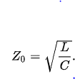
For a lossless transmission line (which is a reasonable approximation for most lines at their designed operating frequencies) the characteristic impedance is
upload_2019-2-5_9-8-5.png
which is independent of frequency and thus can be matched with a resistance at the ends of the line.
See this for a complete explanation.
 

Attachments

Thread Starter

Anastasios Kyriakidis

Joined Feb 5, 2019
2
Because the capacitance and inductance of a transmission line create a combined impedance the appears to be largely resistive.
For a lossless transmission line (which is a reasonable approximation for most lines at their designed operating frequencies) the characteristic impedance is
View attachment 169520
which is independent of frequency and thus can be matched with a resistance at the ends of the line.
See this for a complete explanation.
You 're the best, thanks!
 
Top