
Hello,
I have problems with driving a coil with a 20KHz signal. I made some tests and will attach them to this thread. My setup is as follows: An AD9833 is used to produce a 20KHz 5Vpp square wave. Now someone on this forum told me to either use a buffer amplifier or a mosfet to drive a coil. The coil in question is one of those. It is 3 coils wrapped orthogonal to eachother. At the moment I only try to drive one.
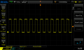
I tried the mosfet variant and ended up with the results in the attachment. The mosfet basically peaks to a very high voltage and isn't stable at all.
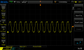
Then I tried using an op amp. First thing I noticed is that it has some problems with slew rates, I think that is what it is. And the voltage across the coils are unsatble as well.
If you have any opinions on what to change, I highly appreciate them.
My goal is to drive one coil only. I will time multiplex the signal in the end.
thanks,
8dm7bz
I have problems with driving a coil with a 20KHz signal. I made some tests and will attach them to this thread. My setup is as follows: An AD9833 is used to produce a 20KHz 5Vpp square wave. Now someone on this forum told me to either use a buffer amplifier or a mosfet to drive a coil. The coil in question is one of those. It is 3 coils wrapped orthogonal to eachother. At the moment I only try to drive one.
I tried the mosfet variant and ended up with the results in the attachment. The mosfet basically peaks to a very high voltage and isn't stable at all.
Then I tried using an op amp. First thing I noticed is that it has some problems with slew rates, I think that is what it is. And the voltage across the coils are unsatble as well.
If you have any opinions on what to change, I highly appreciate them.
My goal is to drive one coil only. I will time multiplex the signal in the end.
thanks,
8dm7bz
Attachments
-
 10.1 KB Views: 28
 -
 37.4 KB Views: 29
 -
 12.4 KB Views: 22
 -
 32.8 KB Views: 23
 -
 16.6 KB Views: 23
 -
 33.3 KB Views: 23
 -
 11.5 KB Views: 23
 -
 35.7 KB Views: 22
 -
 9.8 KB Views: 23
 -
 32.6 KB Views: 19

")


