Facebook
 Google
 GitHub
 Linkedin
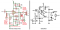
For experimental purposes, I would like to connect an audio amplifier module (see typical circuit below) to various non-conventional inputs and loads. For example, unpowered air coils with very low resistance/inductance. Without load compsensation these would be a dead short.
My concern is how to satisfy the input and output impedance specs of the amp, and effectively make it bomb-proof while still getting a degree of amplification.
Would this best be achieved by inserting mini coupling transformers, e.g. 3K:3K input to ground and 8R:500R across the output? In this case, would C1 still be needed?
Or can I simply place a 3K and 8R resistor in series with the "loads" to ground at the in and out respectively?
If both would work, I would like to please understand what are the pro's and con's of each approach in terms of the amp's performance. Or is there a better method?