hi Arien,
Welcome to AAC.
Which type of light did the flasher unit drive, eg: LED or tungsten etc.??
We need to know the details of the input/output voltages etc.
We maybe able to suggest an alternative MOSFET/BJT
E
With some rash assumptions, it looks like the Source is connected to ground/com and the Drain (tab) is to load. That would be common for an N-channel mosfet. Like Eric said, if other factors allow you to estimate the current and voltage requirement, we might be able to suggest something that will work but with a different part number.
hi Arien,
Welcome to AAC.
Which type of light did the flasher unit drive, eg: LED or tungsten etc.??
We need to know the details of the input/output voltages etc.
We maybe able to suggest an alternative MOSFET/BJT
E
It's a 12V motorcycle turn signal flasher. There are two capacitors and what I think is a variable resistor on the back side. Thanks a ton for the reply; I'm only in my second quarter taking prerequisites for electrical engineering so I know hardly anything about circuits. I'm trying to integrate a flasher circuit into a PCB that I'm designing using Easy EDA. Self learning what all the numbers and letters mean for each individual part is a little daunting but I'm slogging along. I suspect that I'll learn a ton from this forum, so I'm very grateful that you're taking the time to help me.
hi Arlen,
As its a12Vdc system , I would say a N-MOSFET rated at least 25Vds and say 10A would be OK, choose a MOSFET with a Gate Vthresh of approx 5V.
Once you have the project working you can optimise the choice of N-MOSFET.
E
With some rash assumptions, it looks like the Source is connected to ground/com and the Drain (tab) is to load. That would be common for an N-channel mosfet. Like Eric said, if other factors allow you to estimate the current and voltage requirement, we might be able to suggest something that will work but with a different part number.
I replied to Eric's question with some more details and photos. Thank you, suggestions for alternative parts would be very helpful. I'm trying to teach myself Easy EDA to design a pcb for a prototype I'm building. Alternative suggestions for the best way to have a circuit board made are also welcome. I am trying to teach myself AutoCAD Electrical, but it looks like easy EDA has a feature where I can draw a schematic, convert it to a PCB layout and have a printed circuit board sent to me in the mail. If it's not obvious, I'm in way over my head, designing the PCB is the last (and for me he most difficult) phase of my prototype.
hi A,
I would recommend that when you have completed copying the circuit diagram as laid out in the original PCB track copper, that you post the diagram.
We can then refine our guesswork.
E
The mosfet you show is distinguished by the clipped center lead (Drain) in what approximates a very common TO-220 package with a clipped center lead. Some of the packages that come with a clipped lead at TO-268, TO-263, and TO-252.
Any of those devices rated for 25 Vds or more as Eric suggested will certainly be able to handle the wattage of your light. In fact, you are likely to see current ratings far in excess of what you need. In other words, there are a lot of likely substitutes.
Digikey (digikey.com) is one of the popular suppliers in the US. It has a pretty nice parametric search engine where you can search on N-channel mosfets by package type. Find sort of what you need, then search for suppliers in your county to get your substitute.
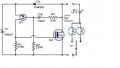
What I'm trying to design is a 12 volt LED turn signal flasher; I posted some more photos and details on Ericks comment above. I've been studying and drawing this schematic that I found online to try to wrap my head around how the circuit works. So far, I've learned a little about drawing schematics, but I'm too dense to understand what's happening to the electrons/holes moving through the circuit. I've been watching videos on how transistors and capacitors work. I think I understand the transistor labeled Q1, but I don't understand what's happening in the component labeled Q2. Am I correct in thinking it's some sort of mosfet? To be honest I don't yet understand the difference between a transistor and a mosfet. I also haven't yet wrapped my head around how this schematic relates to the photo of the circuit that I attached. I do know that I want to be able to vary the flash frequency, and I think they accomplished that using a variable resistor labeled 502 or 205 on the 12v motorcycle turn signal flasher that I attached a photo of. Tonight, after my math test that I'm supposed to be studying for, I will try to draw a schematic of the circuit board. (more photo's posted on Eric's comment)
... I don't understand what's happening in the component labeled Q2. Am I correct in thinking it's some sort of mosfet? To be honest I don't yet understand the difference between a transistor and a mosfet.
Yes, Q2 is an N-channel MOSFET. It's being used here as a switch, like a relay. That is, it's either on or off. R1 pulls the gate low to turn it off when Q1 is not conducting. When Q1 conducts, the gate voltage rises above the source voltage, and the MOSFET turns on, completing the circuit for the lamp.
Are you sure the schematic is correct? It would be more typical for the source to be at ground, and the lamp current to flow into the drain. I guess this is configured to blink and I'm not seeing how that works.
I think so. Would that be an N-CHANNEL ENHANCEMENT MODE POWER MOSFET? https://datasheetspdf.com/pdf/1257114/AdvancedPowerElectronics/AP60L02H/1
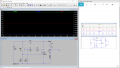
I couldn't find any information on the AAY component, I'm guessing it's a transistor. I'm going to try building the circuit on the above diagram, but I still don't understand how the two transistors are playing off one another. I tried to build it in LTspice, but my output was a steady voltage. I'm not sure what I'm doing wrong. The screenshot shows the circuit done correctly on the right, which I tried to replicate.
 Facebook
 Google
 GitHub
 Linkedin


")


.png")


