 Facebook
 Google
 GitHub
 Linkedin
Hi,
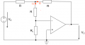
I'm stuck trying to find and explanation for a given solution to an OP-Amp exercise:

The goal is simply to find an expression that connects the output V_O to the input V_S.
This is the solution provided:

Is that solution correct? There's no explanation to it and the only way I can make sense of it is this:
Thanks a lot
I'm stuck trying to find and explanation for a given solution to an OP-Amp exercise:
The goal is simply to find an expression that connects the output V_O to the input V_S.
This is the solution provided:
Is that solution correct? There's no explanation to it and the only way I can make sense of it is this:
- No current can flow through the I_1 branch, because
- R_x is in parallel to the inputs of the OP-Amp
- In the ideal case, the inputs have the same voltage
- Therefore no voltage can drop over R_X, so no current can flow there either
- Since no current can flow through the inputs of the OP-Amp, the entire I_1 branch can't have current and is therefore irrelevant
- Current can flow through the I_2 branch
- (I guess from the end of that branch to the +-Input of the OP-Amp?)
Thanks a lot
Attachments
-
 25.6 KB Views: 2


