IDC 10-pin I2C connector

Thread Starter

STech2106

Joined Jul 8, 2023
43
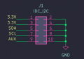
I would like to use an idc connector to carry i2c signals and 3.3v power supply and an auxiliary signal, is there a usually used pin allocation topology? For instance the first 5 pins of the top line connected to the bus and power supply pins while the bottom ones all connected to gnd?
 

MrChips

Joined Oct 2, 2009
34,655
It is customary to use dual row IDC connectors with one row entirely dedicated to GND. This would make all signal lines on the other side to be separated by a GND wire. This reduces cross interference. Note that power wires provide the same separation as GND wires.
 

MrChips

Joined Oct 2, 2009
34,655
GND is a low impedance path for AC signals.
And so is the 3.3V if it has proper decoupling capacitors installed. They both provide shielding to minimize cross talk interference.

The schematic you posted looks good.
 

Thread Starter

STech2106

Joined Jul 8, 2023
43
Hi @MrChips ,

thinking about my problem again, I realized that there is no right-angle IDC connector. I would like to make a connection similar to the one in the picture. I need a connector that has a locking system and can only be inserted one way. Do you know of any?
 

Attachments

MrChips

Joined Oct 2, 2009
34,655
What do you mean "there is no right-angle IDC connector"?

1743432711038.png

This one is keyed so that you can only plug in the cable one way.
I would not use board to board connector because the lack of movement will cause problems . I would use a ribbon cable instead.
 

Thread Starter

STech2106

Joined Jul 8, 2023
43
@MrChips

The one you attached is a male IDC connector. There is no, or at any rate it is difficult to find a female connector that could plug into the male. In your experience does a rigid pcb to pcb connection create problems in the long-term?

My fear is to stumble upon problems related to EMI interference and given the cable to add capacitance to the I2C bus , are my fears baseless?
 

MrChips

Joined Oct 2, 2009
34,655
Female connectors are available. This just an example:
https://www.digikey.com/en/products/detail/samtec-inc/FFSD-05-D-04-00-01-N/4381807

I once had to diagnose and repair an instrument where two boards were rigidly connected to each other via card edge connectors. The boards were screwed down instead of being allowed to float. I know that this is a different situation but I don't like that idea of two horizontal boards plugged into each other. Ribbon cable connectors provide freedom to float. Think what happens when the assembly is subjected to vibrations.

Inter-cable capacitance work to your advantage in this case. Keep the cables short, under 10 cm, and you would not have any problems.
 
Top