I want to control motor speed with capacitors

Thread Starter

mtalent

Joined Oct 2, 2017
30
I am sorry .......

Yes I want to replace the mechanical switch with an electronic switch that I will control over the net with an mqtt. If I didn't say that at first it's because I am working with several sites trying to get help and I forget what I told who.

You guys have been by far the most helpful, I spend hours in other forums explaining bulsh!@## anyhow you guys got me where I am now. I have a schematic done which shows how I intend to replace the mechanical switch. here it is ----


I am sorry I am not the best at this (schematic making). What I guess I will be doing is having a fan sent to me by a customer, removing the mechanical switch and replacing it with mine. Then boxing it up real nice and forwarding it on to them to be installed at which point they buy my android/ios mobile app (in alpha) which will control the fan and other things (led lights etc) in their backyard experience. From other sites it appears that me replacing the switch may void the ul rating ...... question can I get my switch ul certified so all I do it replace the mech switch and the fan is still certified.
 

Thread Starter

mtalent

Joined Oct 2, 2017
30
I should add that most other sites wouldn't help me, oh ya can I use a triac/optocoupler instead of these bulky switches????
 

Thread Starter

mtalent

Joined Oct 2, 2017
30
Ok I need help again, my diagram is nice and it is helping me but I am still a little confused trying to follow the power here.

just for a refresher here is the cap


in the pull chain mechanical switch seen below.


the house power black wire goes to switch position L

Brown wire from capacitor to switch position 2.

Purple wire from capacitor to switch position 3

Gray wire left side of capacitor pack goes to switch position 1

The other Gray wire from left side of capacitor pack goes directly to reverse switch

Red wire from capacitor pack goes directly to motor.

Ok my thinking is that the gray wire going directly to the reverse switch eventually makes it's way to primary coil

Red wire is going from capacitor pack to secondary coil no switch

Now I am having some problems with the purple, brown, gray wires going to switch. And how to include them in my electronic relay.

The second gray wire is not connected to a capacitor and there are two of them where would I connect this wire to my switches. I was originally thinking that I would switch house power to the brown and purple wires but then how does that get to the secondary winding.

The three place switch has house power and the gray wire and the purple and brown going in. I have been trying to find a switch wiring schematic but not much luck.

Maybe I connect the gray to the black and the purple to the brown (not likely but man I am killing myself here I don't understand the flow of the current through the caps pack).

I have two switches/relays in my setup which should work for this setup. because my thinking is low is both switches off, medium is one switch activated and high is both switches activated. When I cut the mechanical switch out I am going to have 4 wires and my switches allow 3 (so am I going to connect two of them together or am I wrong and I need another relay).

Any help would be appreciated thanks all
 

Thread Starter

mtalent

Joined Oct 2, 2017
30
I found this if it helps.....

Most likely a capacitor needs to be in series between the incoming power and the motor winding. In the case of my fan, as described in the previous paragraph, this means connecting a capacitor in series between the black and gray wires. The speed switch will also be involved of course, since it will determine which capacitor(s) are connected between the black and gray wires.
 

MaxHeadRoom

Joined Jul 18, 2013
30,772
As to the UL rating, I would think if you keep everything isolated via opto isolators, you would need one for each speed.
The capacitors are in series with the winding, as per your OP.
You do not require random phase couplers, but zero crossing type, such as MOC316x/308x for example.
Max.
 

Thread Starter

mtalent

Joined Oct 2, 2017
30
thanks Max,

I purchased these .....

Major Brands MOC3010 Triac Optocoupler, AC Output, 1 Channel, 250VDRM, 6-Pin, PDIP, 4 mm H x 7 mm W x 7.62 mm

I wasn't sure which ones to get. I just checked the data sheet for these and it says (link below)

https://www.jameco.com/Jameco/Products/ProdDS/26278.pdf

"non-zero crossing"

I will try to get some of the zero crossing today. I will research the difference. So you think if I build the switch with these replacing the mechanical switch I could keep from voiding the UL or could get my own UL.

Still trying to figure out the wiring/switching, I think I have the power flow (black to gray) adding the caps in series to increase fan speed.

thanks again all

Mark
 

wayneh

Joined Sep 9, 2010
18,133
...you would need one for each speed..
It's worth noting that eliminating the mechanical switch opens the possibility to have more speed settings. Every possible combination of the capacitors might provide a few useful settings that were not previously available. But I wouldn't advise combinations that exceed the original peak capacitance. This might send too much current into the auxiliary coil. I gather that some fans simply eliminate the capacitor altogether to get top speed, and in that case you could use whatever capacitance you want.
 

MaxHeadRoom

Joined Jul 18, 2013
30,772
thanks Max,

I purchased these .....MOC3010

Mark
Yes those are random phase switching which is not what you want, also there is no need for any PWM output.
You can just leave the trigger output high for the duration of the ON time.
These are PSC (permanent start cap) motors where each winding is identical, you can actually reverse them if needed, as in the large ceiling fans that have opposite direction choice for summer/winter.
The one posted appears to be of that type.
Max.
 

Thread Starter

mtalent

Joined Oct 2, 2017
30
Ok just purchased these .... Hoping they will work.....

10 Pcs FAIRCHILD MOC3061 MOC3061-M Througn Hole 6-PIN DIP ZERO-CROSS PHOTOTRIAC DRIVER OPTOCOUPLER (600V PEAK)

I was pleasantly surprised in the datasheet it says UL recognized and gives file # and vol.

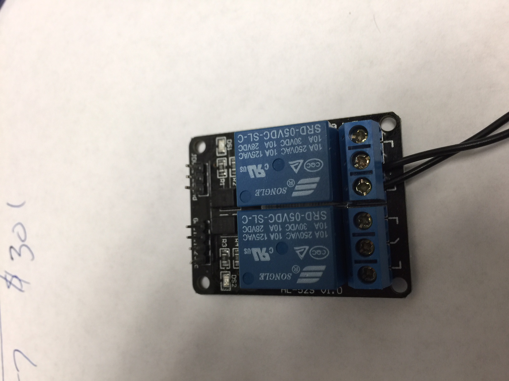
Ya more speeds should be simple by controlling the capacitor level. I am still swimming in figuring out the switching setup, right now I have the big bulky blue box relays which should be sufficient for testing (shown below). Sorry it's so big


what to connect to no and nc and the load, I am reading and working (this is fun right). Once I get this all figured out and get the optocouplers I think I can put this thing together and move on

whew
Mark
 

MaxHeadRoom

Joined Jul 18, 2013
30,772
If you intend using relays they will be isolated anyway??
There would not be Triacs involved, and IF any opto's were use d they would be of a different type!
Also you should confirm if the reversing option is part of the fan.
Max.
 

Thread Starter

mtalent

Joined Oct 2, 2017
30
I am sorry max I am using the relays just as a test setup (I don't have the triacs), I want the completed product to be solid state and controlled with something like what you are describing. Yes the fan is reversible, my thinking was that as long as my switch does exactly what the original mechanical switch the fact that the reverse switch is in the system shouldn't be a problem.

the second gray wire from the caps pack goes directly to the reverse switch which has 6 wire connection. The two in the middle are the gray from the caps pack (middle left side) and a white (I guess neutral) (middle right side) then the top two and the bottom two are opposites of each other on top left yellow right pink and bottom set are left pink right yellow.

So the FAIRCHILD MOC3061 MOC3061-M Througn Hole 6-PIN DIP ZERO-CROSS PHOTOTRIAC DRIVER OPTOCOUPLER (600V PEAK) ----- WILL NOT WORK ?????????????????????????

I can cancel these and try to get the right ones

thanks all

Mark
 

Thread Starter

mtalent

Joined Oct 2, 2017
30
OK cancelled the ones I had ordered and got this one which I believe should be the right one

MOC3162M

I hope I have cleared up any confusion and thanks again

Mark
 

MaxHeadRoom

Joined Jul 18, 2013
30,772
Yes, for your application you just want/need on-off control, NOT phase angle control, therefore you need the zero crossing MOC3061/2 type.
For reversing you just need a pair of Triacs, the issue now is that you are going to have Triacs in series, this usually requires simultaneous switching, see ONsemi app note 1045/D.
Max.
 

Thread Starter

mtalent

Joined Oct 2, 2017
30
bucko.mtalentlive.com/switch_diag.jpg

above is a link to the picture it is not coming out big enough to read

Ok here is my thinking..

All switches off power flows from house directly to gray from caps pack without any capacitors. This should power the motor with the 4.5uf red wire from caps pack that is not switched but always connected (low).

Switch 1 and 2 on 3 off power now flows from house to purple to gray from caps pack this should include the 5uf capacitor giving us 9.5uf total and a higher speed (medium).

All switches on power now goes from house to purple to brown to gray from caps pack includes all caps and should have 15.5 uf an a higher speed (high).

I wanted to do it with 2 switches and I don't like connecting the gray in two places but I couldn't figure out a better way to do it. (I am guessing you guys have a better way??? or not :) )

I only have 2 switches right now so I may not be able to set the whole thing up (I have more switches coming tomorrow)

I also want to add that these switches are just for prototyping and the final product with be switched with solid state zero crossing optocoupler/triac 3162M's to make it all nice and safe and UL approved

thanks
Mark

I attached picture of switches if it's easier to read that way
 

Attachments

Thread Starter

mtalent

Joined Oct 2, 2017
30
Oh ya Max and Wayne did we come up with anything on the 3162M's not able to handle a load. Do I need something else ???

Thanks Guys

Mark
 

MaxHeadRoom

Joined Jul 18, 2013
30,772
For three speeds plus reverse, I see at least 5 Triacs, IMO it would have been better to develop a speed control that uses the high speed (optimum) cap, and experiment with burst firing (not phase control) the motor on off for a very short variable length periods, This would still require 3 Triacs to include reverse.
I was in the process of looking at this possibility but had to shelve it temporarily due to another project cropping up.
MOC3062 should work.
Max.
 
Top