Facebook
 Google
 GitHub
 Linkedin
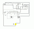
I have make this circuit in circuit wizard
In this circuit a 240/12 V(india 50 Hz AC supply) transformer is used, in this circuit a relay turn ON a MOSFET and mosfet turn ON the relay no.2 which make turn on a 240 V 10 W light bulb.
But I have very elementary knowledge of electronics
When I simulate this circuit in circuit wizard software with explosion on most of them components got damaged.
Please suggest some solutions or mistakes in this circuit.
I have to make a circuit for training purposes of unschooled electricians.They have to work on live 440V line(with rubber gloves) in a electricity distribution company without interrupting the consumer supply.So I am trying to make some circuit when there is a short circuit in electrical network while working.It give a indication or sound or both.Please help me to build it.
I have done electrical diploma.just giving idea! For my understanding level......
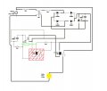
Attachments
-
 90.2 KB Views: 26