 Facebook
 Google
 GitHub
 Linkedin
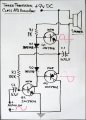
I'm currently doing just that. Just trying to find two 1n4148s. If this ab circuit works then I plan on using to to drive transistor banks. Hopefully it'll give me at least another 5 watts. Not shooting for the moon when I can see it from earth. I figure when my oscilloscope gets here I'll be able to do more with what I have knowing how it's working. This ab I tried last night and didn't work but I already know I didn't have the right diodes.You can adjust the current through the TIP41/42 by adjusting the quiescent current (idle current) or Q-point (bias point)of the transistor. In effect what you are doing is changing the class of the amplifier, from class A to AB to B. You are inviting higher cross-over distortion as you go from class A to AB to B while improving power efficiency.
In any case, you still need to put heat sinks on the TIP41/42 for higher power output.
If you wanted a straight transistor design and not use the LM386 then you can go with a four-transistor design consisting of a pre-amp, driver, and push-pull output. If that is what you want with the TIP41/42 as output I can come up with a design but not today.
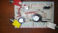
I am not a audio amplifier design expert but I can slap together a simple four-transistor circuit that will work. I rarely do simulations but prefer to work with a real circuit and see how well it performs.
Would creating a preamp accomplish that? Say a well build class a?Of course it would not sound louder. By increasing the supply voltage to 50V you have given the amplifier more headroom so that it no longer clips. In order to sound louder you have to increase the input signal without introducing clipping.
Makes sense. I'm working on a class ab right now with transistor banks to share the load as a slightly higher power pretty amp for a power amp I'll try to build later. At the moment it's just a proof of concept circuit.because the very simple circuit has nothing to adjust for the correct amount of current in the output transistors. The diodes and emitter resistors work when the supply voltage is low.
Last edited by a moderator:


")


