I made a pair of headphones

Thread Starter

Hamlet

Joined Jun 10, 2015
553
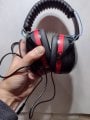
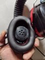
I doubt they're audio quality, but I'm not an audiophile, so who cares. This is how I did it: I got some early protector muffs, and wired in two old style telephone handset ear pieces in series, and ran a 3.5mm line out .

They seem pretty sensitive to my poor ears. When I brush voltage across the plug,
I can detect clicking down to.02v, the lowest my bench top supply goes. On my LCR Meter, they scream at the 1k setting, showing an impedance of 0.3k.

I built them for small signals, radio builds, and the like.

Tell me what you think, what kind of performance they're good for, ie. crystal radios? And what can improve them. Initially, they seem very sensitive, but I don't know if I can do better, achieve hi-z performance, etc.
 

Attachments

MisterBill2

Joined Jan 23, 2018
27,181
What I have read is that at least some types of telephone transducers are the best performers for crystal radios. So that is one application for them. Next, since the phone system designers have done a whole lot of research on what provides the best communication audio frequency response, those phones should work quite well for audio communications listening. They are not "Hi Fi" by any means, but that only matters with music, at most.
And not much need for impedance matching because maximum power transmission is seldom a headphone requirement.
 

Thread Starter

Hamlet

Joined Jun 10, 2015
553
Yes, both good points. Piezoelectric is my next try, maybe today. Max power transfer is nice, but not at all a requirement to optimize.
I'm guessing this might have better response than hi Fi headphones at double the impedance (ie. 600ohms). I find it interesting that telephone ear pieces are so nicely engineered, at .05v, I couldn't measure any current, yet the audio response was very affirming.

I have enough parts to try for two more pairs. I have a couple dozen small 100ohm speakers, perhaps four in series might be pleasing.

Question: do piezoelectric elements do better with some high value resistance across them? I've seen both, in crystal radios and other applications. I don't quite understand why that would help anything
 

MisterBill2

Joined Jan 23, 2018
27,181
Crystal (piezo) transducers are an open circuit, similar to a capacitor. So shunt resistors are used if a DC path is needed for an application. Probably the resistor also damps any tendency toward ringing.
 

Thread Starter

Hamlet

Joined Jun 10, 2015
553
I tried piezoelectric elements, very sensitive, but also harsh, at about a five volt swing. I don't know what value of resistance to try, or whether to place at the piezo elements, or at the source. I'd prefer the source, that way I could utilize for various applications, lower voltages. Bilut the cable inductance might cause ringing. I suppose I could put a switch on the headphones , perhaps rotory, so different resister values could be implemented, depending on sensitivity needs.
 

MisterBill2

Joined Jan 23, 2018
27,181
Consider that piezo disks all have some resonant frequency that undoubtedly has some effect on the frequency response, just like paper cone speaker resonance has an effect on response. Also, they do not show resistive loss either. So the potential for ringing is real. That is why shunt resistors are added.
 
Top