How to use multiple IR avoidence sensors?

Thread Starter

Fixx

Joined May 9, 2023
19
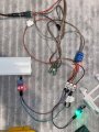
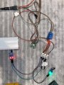
Connected 2 sensors without diodes:
2 Doors open: 5V - Relay off
2 Door closed: 0.18V - Relay on
1 Door open: 0.36V - Relay off

Also tried this; diodes intact, connect 1 sensor via diode and another one directly. When directly connected sensor triggered, relay is on(should be off) and other sensor also lights up as if triggered.

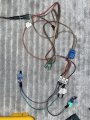
There is 3 white connectors and 3 diodes for 3 IR sensors.
 

sghioto

Joined Dec 31, 2017
8,693
Also tried this; diodes intact, connect 1 sensor via diode and another one directly. When directly connected sensor triggered, relay is on(should be off) and other sensor also lights up as if triggered.
You have to use a diode for each sensor in the test or it won't work. You need to have an obstruction in front of the sensor to simulate a closed door so the output of each sensor is low.
This makes no sense.
2 Doors open: 5V - Relay off
2 Door closed: 0.18V - Relay on
1 Door open: 0.36V - Relay off
 

Thread Starter

Fixx

Joined May 9, 2023
19
You have to use a diode for each sensor in the test or it won't work. You need to have an obstruction in front of the sensor to simulate a closed door so the output of each sensor is low.
Yes, I've been using 3 diodes; 3 separate sensor OUT pin goes to 3 separate diode anode, then that 3 diode's cathodes joined together and feeding relay's IN pin.

When both IR sensor obstructed, sensor's;
VCC-OUT: 4.80V
GND-OUT: 0.17V
 

sghioto

Joined Dec 31, 2017
8,693
Something is wrong here. I see different colored LEDs on the modules. Test each module separately to see if the output measured from ground is the same with and without the obstruction.
 

Thread Starter

Fixx

Joined May 9, 2023
19
I got identical 3 sensors for my setup.

For this test, LED are different color but remain is identical on 2 sensors, also logic behaviour is same.

It's got too late in my country, thanks so much for your interest and efforts. I really can't understand the behaviour of this simple circuit, but try to understand it saturday. Good day for you, wish to continue this issue saturday.

EDIT:I have breadboard and want to test just simple setup (3xsensor, relay, 3xdiode) on it, but have no knowledge on breadboard usage. I mst first learn it.
 
Last edited:

wraujr

Joined Jun 28, 2022
260
What I see:
The sensor module output will be LOW when IR obstructed (i.e. door closed)
But, the relay module needs LOW input to activate relay.
So with the or'ing diodes, logic says all the 'or' inputs must be low to get low output and engage relay.
So this means with all three doors closed, the relay is active and his light would have to attach to the NO connections.
Opening any one or more doors, drives the relay module input high, turning relay off.
Don't like this as relay is active 24/7 except when door(s) opened.
So you really need a NOR function, hard to do with just diodes....
 

sghioto

Joined Dec 31, 2017
8,693
Actually, the board with the relay has a transistor driver so it is active HI to turn the relay on
Actually that is most likely not correct. After further research I found an identical looking unit that says it requires a low input to activate.
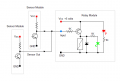
In order to duplicate the operation in the 3 photos in post #26 the diodes must be reversed with the cathodes going to the output of each sensor as shown in the schematic below.
Either or both sensors LOW relay is ON.
Both sensors HIGH as in photo #1 relay OFF.


1683849078453.png
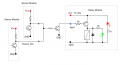
For correct operation it would need an inverter with diodes reversed as shown if using said relay module so the
relay only activates when any door is opened.
1683850159295.png
 

MisterBill2

Joined Jan 23, 2018
27,780
If the sensors are active low, meaning that they pull the "DATA" output down to the supply common when active, the why not just change the arrangement? Connect one side of the relay to the positive source and let the data output pull the other side low to operate the relay. No inversion stage required. And of course the diodes will need to be reversed. But now there are conflicting reports as to what levels are required.
So now I am suggesting that the TS should measure the voltages instead of people guessing and assuming what they would be. The voltage measurements will be referenced to the negative of the 5 volt supply.. The first measurement will be with one sensor connected and the doors closed. REad the sensor supply voltage and the sensor DATA voltage. Then open the door and read the sensor output voltage. Then open the one door and read the sensor output and supply voltages. And does that operate the light? Then, without disconnecting the first sensor, power the second sensor and measure it's output with it's door closed, and then with it's door open. Then with the second door closed and the first door open and it's sensor connected, measure the sensor data voltage , and then the input to the relay module with the first sensor connected. After that, without changing anything, connect the output of the second sensor to the really module and note what happens with the module input voltage. AND check the 5 volt system to be sude it has not changed.
The purpose of this test is to see if the sensors have high impedance outputs in the OFF state or not.
 
Last edited:

sghioto

Joined Dec 31, 2017
8,693
So now I am suggesting that the TS should measure the voltages instead of people guessing and assuming what they would be.
Thats already been done. We know that the output from the sensors are Low when the doors are closed. The output is High when a door is open which is not compatible with the existing relay module being used. So need an inverter or a relay module that requires a high input.
 

Thread Starter

Fixx

Joined May 9, 2023
19
Thats already been done. We know that the output from the sensors are Low when the doors are closed. The output is High when a door is open which is not compatible with the existing relay module being used. So need an inverter or a relay module that requires a high input.
Thanks so much for your help.

How can I build an inverter?

Or I'm already wanting to use Solid State Relay but cannot find a suitable one for DC voltage domestically, need to order from Aliexpress which means time.

Or I can use Arduino, overkill but it should work, right?
 

MisterBill2

Joined Jan 23, 2018
27,780
Thats already been done. We know that the output from the sensors are Low when the doors are closed. The output is High when a door is open which is not compatible with the existing relay module being used. So need an inverter or a relay module that requires a high input.
We are also told that it works as intended when only one sensor is connected! If that is the case, then no inverter is required. If the logic sense is able to operate when only one is connected then it should be correct for all three.
Diode isolation should work, but as the results were not as intended then some incorrect connections are what I would suspect as being the cause. Or perhaps diodes with problems. Consider that it is quite possible to damage a diode while soldering to it. And all sorts of problems can hide under heat shrink tubing.
What is not clear is why a module with other components was selected instead of just a simple relay
 

Thread Starter

Fixx

Joined May 9, 2023
19
Thanks but still IR sensors' logic is faulty, otherwise I can simply change relay's output to NC. I will put all components on breadboard clearly tomorrow, and measure voltages.
 

sghioto

Joined Dec 31, 2017
8,693
Thanks but still IR sensors' logic is faulty, otherwise I can simply change relay's output to NC.
I wouldn't call it faulty it's just that the two modules are not directly compatible in this particular application. To make it work properly with the relay module you have now will require adding the inverter circuit which is comprised of a single NPN transistor like a 2N3904 or similar.
I wouldn't want to use the NC contact and have the relay activated when the doors are closed.
Even if you get a SSR or different relay module it will still require the 3 diodes.
 

wraujr

Joined Jun 28, 2022
260
I wouldn't call it faulty it's just that the two modules are not directly compatible in this particular application. To make it work properly with the relay module you have now will require adding the inverter circuit which is comprised of a single NPN transistor like a 2N3904 or similar.
I wouldn't want to use the NC contact and have the relay activated when the doors are closed.
Even if you get a SSR or different relay module it will still require the 3 diodes.
or he can get a different relay module and eliminate need for "inverter"
There are relay modules with a jumper to select high or low trigger.
https://www.amazon.com/HiLetgo-Channel-optocoupler-Support-Trigger/dp/B00LW15A4W/ref=sr_1_3?crid=27X65ZNF6LEEI&keywords=relay+module&qid=1683888816&sprefix=relay+module,aps,89&sr=8-3
 
Top