how to use instrumentation amplifier AD620?

ericgibbs

Joined Jan 29, 2010
21,489
hi,
The problem when using a single supply with a AD620 or 623 is that the Vout will never be able to be less than approx +0.7V.
The LM324 is capable of getting close to 0V out when connected to 0V via a resistor,

If you have a +12V supply that is being used supply only this part of the project, you could use a LM324 OPA to give a 'Virtual Earth', this would give approx a +/-6V dual supply.

What power supply do have on the project.?

E

EDIT:
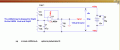
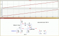
This is an example of a virtual Ground, using the LM324 to give +/-6v from an isolated supply of +12v
 

Attachments

Last edited:

ericgibbs

Joined Jan 29, 2010
21,489
hi,
Which part of the circuit don't you understand.?

You could use the 12v and 6v power supplies to dual power the circuit, but the PSU outputs must be 'floating', ie: not connected to the Chassis of the PSU or Ground.
 

Attachments

ericgibbs

Joined Jan 29, 2010
21,489
hi,
Running further simulations, taking into consideration that the LM324 has 4, OPA's sharing a common 0V rail.
When one of the 4 OPA's is configured to provide a Virtual Ground, it imposes limitations on how the remaining 3 OPA's can be configured.
The limitations differ when the VG, OPA's 0v is connected to VG or the power supply negative.

E
 
Last edited:
With the "talk" about micro-controllers in this thread, you can have absolute measurements and measurements to 1/2 Vcc (of the controller)
Vref is told to be 1/2 Vcc. That is where Vref of the IA can be helpful. In most cases Vref of the IA has to be driven by a low impeadace (spelle d out in the datasheet)

Most car sensors use 1/2 Vcc are this way. The rails or the power supply voltages have traditionally been hard limits (hence rails). With some LT parts the inputs can exceed the rails. Generally, you can almost reach them, but not quite. The automotive sensors might be linear from say 0.1 to 4.9V and zero will be 1/2 Vcc. The 1/2 Vcc point can move with power supply noise, but the digitized output would not.

This saves you from needing a precision reference.
 

Thread Starter

ahmedzaidan

Joined Jul 22, 2017
39
Hi All..

I have two questions .
1.can I use the load cell without using the two resistors to complete the bridge ? If not why?

2.my friend told me that i cant use lm741 op amp with load cell without explaining the reasons for that.
Is this true ?


If yes why?
 

Thread Starter

ahmedzaidan

Joined Jul 22, 2017
39
Thanks a lot Eric :)

What are the advantages of using ad620 instead of lm741?

How did you choose the resistors' values in the last circuit ?

:)
 
Last edited:

ericgibbs

Joined Jan 29, 2010
21,489
hi,
The AD620 is specifically designed for amplifying low level differential voltage signals which have a high common mode voltage.
The internal resistors are matched so that the gain is linear over a wide CMV range and temperature.

A LM741 is a poor choice, its old and has a low level specification.

If you decided to build a INA using regular OPA's you would have to buy matched close tolerance resistors if you wanted a reliable quality amp.

E
EDIT:
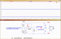
As I do not know your project specification, I choose arbitrary resistor values in order to run a simple demo simulation for a LM741.
 
Last edited:

Thread Starter

ahmedzaidan

Joined Jul 22, 2017
39
hi eric,

thaank you :cool:

our project to amplify the load cell voltage to read it by mcu .
we choose ad620 but yesterday our prof requist from us to use lm741 :( and he told us that it will work fine :rolleyes:.

:)
 

ericgibbs

Joined Jan 29, 2010
21,489
we choose ad620 but yesterday our prof requist from us to use lm741 :( and he told us that it will work fine :rolleyes:.
Hi Ahmed,
I agree with your Prof, it will work, but 'works fine' only means it is good enough for your college project.

I would not use a LM741 in a commercial project, ask your Prof.

E
 

ericgibbs

Joined Jan 29, 2010
21,489
I tried your 741 circuit with 1mv deft input the output was 0.22 v
hi,
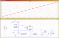
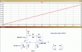
If you recheck the plot in post #34, you will see that the gain of the 741 is set to 10mV in, 1Vout ie: Gain of 100.

How is your 1mV signal connected to the 741,?

E

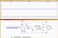
Sim for 1mV input.

EDIT:
Corrected typo, Gain=100 , not 10
 

Attachments

Last edited:
Top