How to trigger a relay based on a resistance drop in a Push to Start Switch

Thread Starter

Restomod

Joined Jan 17, 2026
70
The Com has nothing to do with the relay activating.
Are you saying when power is applied to the circuit the second relay activated without pressing the switch?

Yes.

That was with both relay's wired with A1 top red 12v A2 off the board, COM didn't matter if grounded or not
 

MisterBill2

Joined Jan 23, 2018
27,977
Are you testing the circuit totally separate from the car?? have you verified that nothing else is connected to that wires circuit??
That circuit only triggers when the resistance is above some limit. What is needed is a WINDOW COMPARATOR, which activates when a voltage is between two limits. Above the lower limit and below the upper limit.
 
Last edited:

sghioto

Joined Dec 31, 2017
8,737
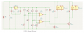
Actually the circuit should be configured as below.
Using fixed resistor to set the trip points at 2.27V on the + inputs of the LM393.
R2 and R9 set the reference at 2.5V on the -inputs on the LM393, making the outputs on the LM393 Low, relays OFF.
When either switch is pressed the reference voltage drops to appx 2.05V which is below the trip point of 2.27V
LM393 output goes High and relay is activated.

1769274017871.png
 

Thread Starter

Restomod

Joined Jan 17, 2026
70
I did this second schematic, the first couple times I put power to the board, the first relay latched, push the botton, triggered the second, but would not un latch.

couple times of that then they stopped responding, not sure why the first latched by applying 12v
 

Thread Starter

Restomod

Joined Jan 17, 2026
70
I think, re reading post #24, the issue is - there is only one Push Button switch.

Activation of this circuit sends signal to crank starter. Hold until engine starts, then release.

A second wire within the same switch - doing the same thing (another LM393 board) turns on the ignition on circuits. Pushing this a second time turns off the ignition circuit.

Both signals off the relays will be inverted to a negative ground trigger of the Infinitybox.com wiring system.

This switch is plug n play to the main system - does not get into any of the can signals.


Keep in mind, this switch and board are not connected to anything else in the car, nor would it be later on - this is the master control to start the car and keep in a run (IGN ON) state.
 

sghioto

Joined Dec 31, 2017
8,737
I think, re reading post #24, the issue is - there is only one Push Button switch.

Activation of this circuit sends signal to crank starter. Hold until engine starts, then release.

A second wire within the same switch - doing the same thing (another LM393 board) turns on the ignition on circuits. Pushing this a second time turns off the ignition circuit.
When the switch is pressed is it momentary or is it push ON then Push OFF?
 

eetech00

Joined Jun 8, 2013
4,723
To be clear.
First push of the switch: relay #2 activates and latches, relay #1 activates but only stays on as long as the switch is pressed.
Second press: relay #2 deactivates, relay #1 does not activate.
This seems like it's describing a "on" "start" "run" "stop" sequence of older automotive vehicles "key" start system.
Off to ON energizes vehicle electrical system. Turning the key to "run" position (spring return) bypasses a resistor that is in series with the battery, providing engine "start" with extra current. Releasing the key, after engine start removes the bypass, lowering current, but vehicle electrical system remains on and engine continues to run. Turning key to OFF position de-energizes the electrical system and stops the engine.

Just an observation...
 

Thread Starter

Restomod

Joined Jan 17, 2026
70
This seems like it's describing a "on" "start" "run" "stop" sequence of older automotive vehicles "key" start system.
Off to ON energizes vehicle electrical system. Turning the key to "run" position (spring return) bypasses a resistor that is in series with the battery, providing engine "start" with extra current. Releasing the key, after engine start removes the bypass, lowering current, but vehicle electrical system remains on and engine continues to run. Turning key to OFF position de-energizes the electrical system and stops the engine.

Just an observation...
If you ever double push, intending to turn off on a modern 2015+ car they do this same thing so that you can have engine off, yet still listen to audio, etc.
 

Thread Starter

Restomod

Joined Jan 17, 2026
70
To be clear.
First push of the switch: relay #2 activates and latches, relay #1 activates but only stays on as long as the switch is pressed.
Second press: relay #2 deactivates, relay #1 does not activate.
sghioto - this how I think this should function.

In this schematic above, there are two trigger wires. How were you thinking that second trigger is made?

Note - my intended switch has two wires that behave the same - open 1000 ohm resistance, Button engaged close 680 ohm resistance.

So if this is the intent - the switch meets this idea.
 

sghioto

Joined Dec 31, 2017
8,737
In this schematic above, there are two trigger wires. How were you thinking that second trigger is made?
In that schematic above there is no latching of relay #2.
I still need confirmation on the sequence of events as posted earlier.

First push of the switch: relay #1 activates but only stays on as long as the switch is pressed to start the engine.
Simultaneously relay #2 activates and latches ON.
Second press: relay #2 deactivates, relay #1 does not activate."
 

Thread Starter

Restomod

Joined Jan 17, 2026
70
Well I must be doing something wrong, I redid the board with fresh components, no response.

If something was shorted we should have seen a spark and all.

On the relays - does it matter if they are connected to system ground or not?
 

sghioto

Joined Dec 31, 2017
8,737
Well I must be doing something wrong, I redid the board with fresh components, no response.

If something was shorted we should have seen a spark and all.

On the relays - does it matter if they are connected to system ground or not?
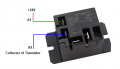
The relays should connect between +12V and the collectors of Q1 and Q2, is this what you mean?
The circuit in post #24 is not going to do what you want as I said earlier, it will not latch relay #2
If the circuit is connected correctly per post #24, both relays will activate and stay activated only while the switch is pressed each time.
 
Last edited:

Thread Starter

Restomod

Joined Jan 17, 2026
70
Sorry - relay topic the COM wires, connected or not connected to GND they did not matter when I did get a relay response yesterday.

I went back through and checked all resistor values to start to ensure accuracy - they were all per #24 post.


Now - I can make two boards, one for the momentary to start the engine, and a second that I will need to test - that one will need to stay on until pushed to shut off.
 

sghioto

Joined Dec 31, 2017
8,737
Correct, the relay COM has nothing to do with activating the relay coil.
The circuit is not that simple.
Latching the Ignition relay is not difficult but the issue will be when then the second push is used to deactivate the Ignition. You don't what the Starter relay activating again though only briefly.
 

Thread Starter

Restomod

Joined Jan 17, 2026
70
You don't what the Starter relay activating again though only briefly.
I agree with that!

I have built (via internet schematics) valved exhaust and wiper emmulators (both GM), so not first time at this so to have a response then nothing I thought perhaps something shorted, better start fresh. Relays work when powered, resistors all verified,

dont know I have the means to reliably test the two diodes
 
Top