How to test TDA7379 audio power amp

Thread Starter

neospam

Joined Jan 13, 2020
110
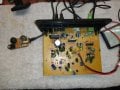
I have a old creative sub computer speaker systems that I believe was hit by lightening spike. Never threw it out and was looking at it. It acts like no power, so far all transistors and rectifier all test good.

How do you test a TDA7379 audio power amp? Can I just probe the output with a scope? I am new to using a scope.

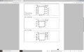
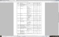
here's all the data on the chip https://www.alldatasheet.com/datasheet-pdf/pdf/192833/STMICROELECTRONICS/TDA7379.html
 

Attachments

MrSoftware

Joined Oct 29, 2013
2,188
Last edited:

Audioguru again

Joined Oct 21, 2019
6,673
The TDA7379 is obsolete and its datasheet shows that it produces only 4W per channel with low distortion or 10W bridged with low distortion into a 4 ohm speaker with a 15V supply. Most of its power output numbers on its datasheet are with horrible 10% clipping distortion. The datasheet says,"38 Whats!"
 

Thread Starter

neospam

Joined Jan 13, 2020
110
my creative power supply makes 12vac, 15?

I will put it back together enough to power it up and probe.

Seems like everything I work on is obsolete.
 

Thread Starter

neospam

Joined Jan 13, 2020
110
TDA7379 has a stand-by pin-out. Looks like 3.5v to trip out of standby? I want to test to make sure this is not stuck in stand-by. Trying to figure out max voltage for the stand-by.

Getting 17+volts at the vcc input pins #3 & #13, that about it. Can I put voltage to the stand-by pin to see if that is a issue?
 

Audioguru again

Joined Oct 21, 2019
6,673
The datasheet shows a standby pin filter capacitor to ground (to reduce POP?) and a 10k resistor to somewhere.
The spec's for the standby pin do not make sense since the block diagram shows it to be the base of an NPN transistor with its emitter grounded.

I think is safe to connect to +17V the 10k resistor that is feeding a small current to the standby pin to allow the amplifier to play.
 

Thread Starter

neospam

Joined Jan 13, 2020
110
Does nothing when I put 17v to the stand-by pin.

When I probe around with a scope (newbie at using) I just get the same sine wave everywhere. Seems weird, could that be power filter/cap? has a liner power supply
 

Attachments

MrSoftware

Joined Oct 29, 2013
2,188
What is the frequency? Is it 60Hz? If yes, then that's the wall power coming through. Try to find an audio tone that is a steady 1kHz and play that to the input. Then start at the input and follow the signal through the circuit until it disappears. Also check the power inputs to the amplifier module to be sure it is actually getting power. If the power supply portion of the amplifier is what died then the amplifier module itself might not be getting any power.
 

Thread Starter

neospam

Joined Jan 13, 2020
110
What is the frequency? Is it 60Hz? If yes, then that's the wall power coming through. Try to find an audio tone that is a steady 1kHz and play that to the input. Then start at the input and follow the signal through the circuit until it disappears. Also check the power inputs to the amplifier module to be sure it is actually getting power. If the power supply portion of the amplifier is what died then the amplifier module itself might not be getting any power.
Thanks for your help. I am new to using a scope and have an older analog scope. Hope it is correct.
2msec time/div
Aligning the start of the wave to the left on centerline, one full wave is around 8.2
8.2x2ms/div=16.4
1/0.0164 = 60.9

I get this wave in everything I check, amplifier, controls, at any point on the circuit board and it looks the same at every point. This test was done w/o any audio signal or signal inputted. Just power to the circuit. I get power to the rectifier, but have not checked pass the rectifier yet.

Should add it tested 17v at the amp tda7379 yesterday at vcc at 2 pins
 
Last edited:

Audioguru again

Joined Oct 21, 2019
6,673
Of course the 'scope probe has a shielded cable and you connected the shield to the ground part of the 'scope and to the ground part of the amplifier.
Because an unshielded single wire is an antenna that picks up the high voltage 60Hz electricity that is all around you.
 
Last edited:

MrSoftware

Joined Oct 29, 2013
2,188
Yes as mentioned above, you're getting the 60Hz from the wires in your walls. Get a tone generator for your phone or computer or something and send a 1000Hz signal and pay attention that one, ignore then 60Hz. An analog scope should be fine.
 

Thread Starter

neospam

Joined Jan 13, 2020
110
Of course the 'scope probe has a shielded cable and you connected the shield to the ground part of the 'scope and to the ground part of the amplifier.
Because an unshielded single wire is an antenna that picks up the high voltage 60Hz electricity that is all around you.
I did not attach the ground to amp ground, just left it off.
 

MrSoftware

Joined Oct 29, 2013
2,188
I missed that part, you absolutely must attach the probe ground to the circuit ground. BUT FIRST, use your volt meter to compare the amplifier "ground" that you're going to attach to, to the ground probe on your scope. The goal is to be sure that what you think is amplifier ground is at the same potential as real ground, because if the voltage is higher than 0 then your scope probe will become a short circuit to ground, which can zap your scope, or whatever the weakest link in the new circuit is.
 

Thread Starter

neospam

Joined Jan 13, 2020
110
Yes as mentioned above, you're getting the 60Hz from the wires in your walls. Get a tone generator for your phone or computer or something and send a 1000Hz signal and pay attention that one, ignore then 60Hz. An analog scope should be fine.
I have a 4700uF to filter the power and from what I tested it is bad. Both of my cap testers do not read that high, so I did the DVM check and it is not charging up, so I presume its bad. There are 2 transistors right after the positive of the 4700uF cap, both of the tested bad. One showed up as a diode (so half maybe working) the other just bad. I thought I tested all the transistors, but I found two hiding under a gob of hot melt when I was removing the power cap. I am not sure what is bad now. The big cap filter power to the TDAamp, those 2 H945 were right off the positive leg also. I did break a small cap removing the hot melt, that needs to be replaced.

I do not have any of these will need to order. So this will be on hold for a few days. very much appreciate your help.
 

Thread Starter

neospam

Joined Jan 13, 2020
110
If the 'scope ground and shield on its cable is not connected to the amplifier ground then the 'scope is simply an antenna that picks up all kinds of interference.
I been discussing this in the scope thread.. whether or not to use a ground, if its necessary and to avoid damaging your equipment. I was under the impression that its not needed a lot of the time.
 

Thread Starter

neospam

Joined Jan 13, 2020
110
I missed that part, you absolutely must attach the probe ground to the circuit ground. BUT FIRST, use your volt meter to compare the amplifier "ground" that you're going to attach to, to the ground probe on your scope. The goal is to be sure that what you think is amplifier ground is at the same potential as real ground, because if the voltage is higher than 0 then your scope probe will become a short circuit to ground, which can zap your scope, or whatever the weakest link in the new circuit is.
Transformer is a wall wart, 12vac 3amp 2 wire. I get both ac and dc off this board all over, little confusing. I took a grd off the rectifier, which seems to be common with aluminum shields and cases on the board. So I believe that is correct grd? I do not want to zap my scope, just learning how to use it.
 
Last edited:

Thread Starter

neospam

Joined Jan 13, 2020
110
If the 'scope ground and shield on its cable is not connected to the amplifier ground then the 'scope is simply an antenna that picks up all kinds of interference.
I can check it later with grd on circuit. Just was not sure if I should connect grd to it.
appreciate your help..
 

Thread Starter

neospam

Joined Jan 13, 2020
110
My tester did not ID the transistors. Not sure if they are NPN PNP BJT. I know 'some' of the other trans tested BJT I tested.

1 - H945 Also has more marks - P 4F 2
2nd - H945 "" P 4K 2
Not sure if they in good enough shape to check for npn pnp with dvm, is there a way to test if they are bipolar?
 
Last edited:

MrSoftware

Joined Oct 29, 2013
2,188
If you can post clear pictures of the parts you're trying to identify, pictures that show the marks, then we can help.

Keep in mind that voltage is relative. Your scope measures voltage on the probe tip relative the ground for that channel. On most scopes, the channel grounds are also connected to the ground in the power cable, so if the ground clip is disconnected then the probe tip voltage will be relative the wall outlet ground (on most scopes, there are exceptions such as scopes with isolated inputs and battery powered scopes) . The net effect of leaving the ground clip off is all that wire in the power cord and the wall becomes an antenna and really affects your readings in a bad way, and the higher the frequency you're measuring the more your reading is affected. So in short, if you want an accurate reading, you must use the ground clip, and clip it as physically close as possible to where you're taking the reading. On a low frequency like 1kHz, any ground point on that amplifier board is probably fine.

This will be helpful :
 
Top