Facebook
 Google
 GitHub
 Linkedin
If you can post clear pictures of the parts you're trying to identify, pictures that show the marks, then we can help.
Keep in mind that voltage is relative. Your scope measures voltage on the probe tip relative the ground for that channel. On most scopes, the channel grounds are also connected to the ground in the power cable, so if the ground clip is disconnected then the probe tip voltage will be relative the wall outlet ground (on most scopes, there are exceptions such as scopes with isolated inputs and battery powered scopes) . The net effect of leaving the ground clip off is all that wire in the power cord and the wall becomes an antenna and really affects your readings in a bad way, and the higher the frequency you're measuring the more your reading is affected. So in short, if you want an accurate reading, you must use the ground clip, and clip it as physically close as possible to where you're taking the reading. On a low frequency like 1kHz, any ground point on that amplifier board is probably fine.
This will be helpful :
Attachments
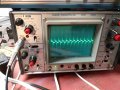
-
 45.1 KB Views: 5
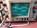
 -
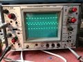
 85.7 KB Views: 5