Facebook
 Google
 GitHub
 Linkedin

We are performing the DC inductive endurance (life) test on a 4-pole electromagnetic relay in accordance with MIL-PRF-83536 and are looking for guidance from engineers who have performed similar testing.
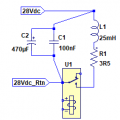
Test Setup
After completing the inductive life test, the relay fails the post-life dielectric withstand test.
While investigating, we monitored the voltage across the relay contacts during contact opening and observed transient voltage spikes of approximately 650-700 V.
Our original test setup had relatively long wiring:
With the shorter wiring, the measured transient voltage reduced to approximately 300-350 V.
This suggests that the wiring layout and associated parasitic inductance/capacitance may be influencing the measured switching transient.
Questions
Test Setup
- Specification: MIL-PRF-83536
- Relay: 4-pole electromagnetic relay
- Endurance requirement: 20,000 DC inductive load operations
- Supply voltage: 28 VDC
- Contact current: 8 A per contact
- All four poles are tested in parallel.
- The load bank consists of one 25 mH inductor and one 3.5 Ω resistor for each contact circuit.
- Operating cycle:
- 0.5 s ON
- 3.5 s OFF
After completing the inductive life test, the relay fails the post-life dielectric withstand test.
While investigating, we monitored the voltage across the relay contacts during contact opening and observed transient voltage spikes of approximately 650-700 V.
Our original test setup had relatively long wiring:
- Approximately 20 m total wiring loop
- Approximately 5 m between the relay and the load bank
With the shorter wiring, the measured transient voltage reduced to approximately 300-350 V.
This suggests that the wiring layout and associated parasitic inductance/capacitance may be influencing the measured switching transient.
Questions
- Has anyone performing MIL-PRF-83536 DC inductive life testing observed contact opening voltages as high as 650-700 V?
- After reducing the wiring length, our transient reduced to approximately 300-350 V. Is this closer to what would normally be expected, or is it still considered high?
- Some other test facilities have reported peak contact voltages of only 100-150 V under similar test conditions without using any snubber, flyback diode, MOV, or other suppression device, since these are not permitted by the standard. Has anyone else observed similar values?
- Can the transient voltage alone be sufficient to cause a relay to fail the post-life dielectric withstand test, or should we also be investigating other possible degradation mechanisms?
- Are there any recommended practices for the physical layout of the relay, load bank, and wiring that minimize parasitic effects while remaining compliant with the intent of MIL-PRF-83536?
- If anyone has reference oscilloscope captures of:
- Contact voltage during opening
- Contact current during opening
- for a 28 VDC, 8 A DC inductive endurance test, I would greatly appreciate seeing them for comparison.