How to stop Tip122 from getting hot

Thread Starter

Don_Fila

Joined Nov 26, 2021
171
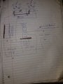
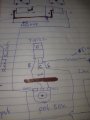
Hello friends I really need your help as an expert on this forum. I have 2 twelve volt relay, which I connected them in parallel and after that I created a voltage regulator using tip122 transistor as a voltage supply which I adjust the voltage to 12v to supply the relay coil with a 12v and also used the reed switch as a switch to activate the relay coil when the reed switch in contact with magnets. Everything works fine, but later and found out that the tip122 is getting very hot so I tried finding out why it's getting hot and I found that when the relay coils are activated that's when tip122 start to get hot but when it doesn't activate it doesn't get hot. So after all the above said tip122 is getting very hot so I decided to use the big heat sink and the tip122 stopped getting hot but it's rather the heat sink that get hot when it stay for some minutes. Please I need your solutions and I want to ask if it's OK to leave the heat sink get hot. Your help will be highly appreciated.20220129_005416.jpg
 
Last edited:

dl324

Joined Mar 30, 2015
16,839
Please I need your solutions and I want to ask if it's OK to leave the heat sink get hot.
Hot is a subjective term that isn't helpful. It's the junction temperature of the TIP122 that's important.

Post a schematic instead of trying to describe the circuit with words.
 

LowQCab

Joined Nov 6, 2012
4,022
A Linear-Voltage-Regulator will always tend to produce excessive Heat, this is normal.

What are You using for a Power-Supply ?
The lower You can reduce the Voltage of the Power-Supply,
the less Heat will need to be dissipated by the Transistor.
.
.
.
 

Papabravo

Joined Feb 24, 2006
21,157
You're head is in voltage mode, as if that was the only thing that matters. Current is the thing when it comes to making things hot. What you need to do is measure the resistance of the relay coil. Two of them in parallel will be one-half of what each coil is individually. so the pair will draw twice as much current. So power, in watts, will be the current squared times 1/2 the resistance of a single coil. That is:

\( Power\;=\;(Current)^2\cdot\frac{1}{2}\cdot(Coil\;Resistance) \)

Consult the TIP122 datasheet to compute the junction temperature as a function of the ambient temperature and the amount of power being dissipated. If the junction temperature is greater than 125 °C, then that would qualify as too hot!
 
Last edited:

AlbertHall

Joined Jun 4, 2014
12,343
You're head is in voltage mode, as if that was the only thing that matters. Current is the thing when it comes to making things hot. What you need to do is measure the resistance of the relay coil. Two of them in parallel will be one-half of what each coil is individually. so the pair will draw twice as much current. So power, in watts, will be the current squared times 1/2 the resistance of a single coil. That is:

\( Power\;=\;(Current)^2\cdot\frac{1}{2}\cdot(Coil\;Resistance) \)

Consult the TIP122 datasheet to compute the junction temperature as a function of the ambient temperature and the amount of power being dissipated. If the junction temperature is greater than 125 °C, then that would qualify as too hot!
That is the power in the relay coils.
The power in the transistor is (Current) * (Input Voltage - 12V)
 

Papabravo

Joined Feb 24, 2006
21,157
You're right, but I think the TS was confused. It seemed like he was saying that there was 12 volts in and 12 volts out, which sounds suspicious for a regulator. It is also not clear if he thinks the TIP122 has some role in voltage regulation. Tough to tell without a schematic. It could be a high-side switch, or a low-side switch, but the current in the coils is the same as the current through the switch. Since we don't know the resistance of the switch we need to measure the voltage across it.
 

Thread Starter

Don_Fila

Joined Nov 26, 2021
171
I think he was confused. It seemed like he was saying that there was 12 volts in and 12 volts out, which sounds suspicious for a regulator. It is also not clear if he thinks the TIP122 has some role in voltage regulation. Tough to tell without a schematic.
No but rather using tip122 as a 24 voltage regulator which I adjust it to 12v for the relay coil
 

Papabravo

Joined Feb 24, 2006
21,157
No but rather using tip122 as a 24 voltage regulator which I adjust it to 12v for the relay coil
See what I mean! I cannot visualize what you are doing from the description and what you are saying makes very little sense. A schematic diagram would be most helpful.
 

Papabravo

Joined Feb 24, 2006
21,157
Your circuit is drawn in an unconventional fashion which makes it hard to see what is going on. I'm going to try and represent it ina more conventional way, but it may take me some time. I'm not going to comment on that circuit. It is hardly what I would call a voltage regulator and it is no wonder the TIP122 is getting hotter than a pepper sprout. According to your particular datasheet, how are the pins on the TIP122 assigned? You need to identify what you think are the base, collector, and emitter. From left to right on the diagram, it should be BCE. Do you agree?
 
Last edited:

DickCappels

Joined Aug 21, 2008
10,153
If you tell us the resistance of the relay coil we can show you how to calculate the temperature rise of the TIP122 over ambient temperature.
And with that we can show you how to specify the heat sink for reliable operation.
 

Thread Starter

Don_Fila

Joined Nov 26, 2021
171
Your circuit is drawn in an unconventional fashion which makes it hard to see what is going on. I'm going to try and represent it ina more conventional way, but it may take me some time. I'm not going to comment on that circuit. It is hardly what I would call a voltage regulator and it is no wonder the TIP122 is getting hotter than a pepper sprout. According to your particular datasheet, how are the pins on the TIP122 assigned? You need to identify what you think are the base, collector, and emitter. From left to right on the diagram, it should be BCE. Do you agree?
 

Attachments

Thread Starter

Don_Fila

Joined Nov 26, 2021
171
Yes
Your circuit is drawn in an unconventional fashion which makes it hard to see what is going on. I'm going to try and represent it ina more conventional way, but it may take me some time. I'm not going to comment on that circuit. It is hardly what I would call a voltage regulator and it is no wonder the TIP122 is getting hotter than a pepper sprout. According to your particular datasheet, how are the pins on the TIP122 assigned? You need to identify what you think are the base, collector, and emitter. From left to right on the diagram, it should be BCE. Do you agree?
Yes
 
Top