Hi everyone. I want to learn hardware design. I want to make 220 Vac/12Vdc (3A) converter . How can I select the transformer, how can I create the circuit ?My aim is to make PCB.
Since you want to use a transformer, I'm assuming that you want to design a linear power supply.
You know the output voltage and current requirement, so you need to decide what rectification method you'll use. That will determine the current required from the secondaries.
Then you'll need to select a secondary voltage. More head room will allow you to use a smaller filter cap. The amount of ripple you can tolerate will determine the ripple current spec for the filter cap.
Do you plan to use a commercially available voltage regulator or do you want to design your own?
Since your intent is to learn, start by using correct labels and capitalization. AC is capitalized because it's an acronym; so volts AC would be written as VAC, not Vac. Without an AC designation, we assume DC, so Vdc should be written as VDC and can be shortened to V.
@dl324 Thanks for your answer.My aim is to learn hardware design and I tried to do linear power supply by myself.I looked for transformer on digikey to use on my PCB but I couldn't find .I didnt understand how to select it.
Why do you think most electrical engineers go to school for years to learn this stuff? There are some who have become good designers with little or no formal electrical engineering training, but those are the very exceptional people. You can probably count the number of people who rose to the top of their field with no credentials on the fingers of one hand.
The transformer and rectification method are related. If you want to use a full wave rectification, you need a transformer with a center tap. If you opt for no center tap, you need to use a full wave bridge rectifier. That uses more diodes and increases slightly the secondary voltage you'll need.
Once you decide on rectification method, you can select a transformer.
I m planning to use full wave bridge rectifier. I only need 12V output with (3A) . I didnt understand which transformer should I select https://www.digikey.com/products/en#cat-11.
I m planning to use full wave bridge rectifier. I only need 12V output with (3A) . I didnt understand which transformer should I select https://www.digikey.com/products/en#cat-11.
The Hammond instructions shown show that a 10VAC/4.6A transformer produces 14.1V peak and the rectifier diodes reduce it to 12.1VDC. The ripple reduces it depending on the value of the main filter capacitor. Without using a higher voltage and a voltage regulator circuit then the voltage will be higher with less load current. But the voltage regulator will eliminate any ripple voltage.
The Circuitstoday power supply does not use a 400V capacitor. The schematic shows where the capacitors are connected.
Maybe they use the 470uF 50V capacitor because Circuitstoday is from India where the electrical system has many voltage problems. I would use a 25V capacitor here in Canada.
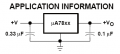
Circuitstoday shows the wrong capacitance for the other two capacitors. The datasheet for the uA7805 shows these values:
No one has mentioned WHAT is to be powered by this 12V Supply.
This makes a huge difference when planning a project.
If cost and complexity are considerations, then why use a printed circuit board ?
Why is it ok to change the design to 1A from 3A, just because it's cheaper or smaller ?
Are you building this Supply just to learn about electronics ?, if the answer is no,
then there are 1000's of factory designed and produced Supplies that you could choose from,
used, surplus, or new, and they would be far safer, more reliable, and resistant to physical damage.
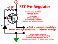
A Linear Voltage Regulator, (if a Regulator is actually needed),
is, in fact, as cheap and as simple as you can get, BUT,
they almost always need a Large Heat Sink to operate, this increases the size and cost of the project.
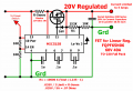
Are you building a "Lab" or "Bench-Top" Power Supply that
needs to have adjustable Current Limiting ?,
or will you simply use a Fuse for protection ??
If you want to build a "Bench-Top" power Supply, see the attached schematics.
 Facebook
 Google
 GitHub
 Linkedin