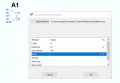
Unused inputs are net-listed as "not present". This is different than gates in real life. There are parameters that you need to set for those gates so it would be best to read the HELP page on them. It also helps to make them visible on the schematic so that it is clear what the behavior should be. Connecting a voltage to the input of an OR gate means it will be ON all the time.
The 'A' devices in LTspice are logic gates and they require an awareness of the settable parameters associated with their proper operation. In your schematic you have chosen a 5-input OR gate with complementary outputs. You have also tied one of the inputs to what looks like 5 volts. This will guarantee the 'true' output will ALWAYS be high and the complementary output will ALSWAYS be low. You must have skipped the HELP page for these devices. That was an ill-advised choice on your part.
The 'A' devices in LTspice are logic gates and they require an awareness of the settable parameters associated with their proper operation. In your schematic you have chosen a 5-input OR gate with complementary outputs. You have also tied one of the inputs to what looks like 5 volts. This will guarantee the 'true' output will ALWAYS be high and the complementary output will ALSWAYS be low. You must have skipped the HELP page for these devices. That was an ill-advised choice on your part.
yes i have removed the 5 volts and kept the other 2 connections but im confused as to why when simulating the output im not getting a pulse, its just staying constant at 0V which obviously means something is wrong
The gate operates as follows:
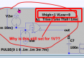
U1 takes a square wave input and produces complementary outputs with an approximate dead time of 1 µsec. The OR gate shows you where the deadtime occurs.
You have your OR gate configured for 1V logic, but your power supply is 5V. Change the Vhigh setting in your OR gate to Vhigh=5.
Right-click the MOSFET symbols and swap those default MOSFETs for 'proper' ones from the provided library.
You have your OR gate configured for 1V logic, but your power supply is 5V. Change the Vhigh setting in your OR gate to Vhigh=5.
Right-click the MOSFET symbols and swap those default MOSFETs for 'proper' ones from the provided library.