How to run a 4017 (Decade Counter) once and then stop?

GopherT

Joined Nov 23, 2012
8,009
Oh. Did he mean, "with this timer circuit"?
Well, an SCR would probably work.
I assumed he was still talking about his timer circuit but he was also talking about some pulses. He wouldn't have pulses if his circuit stops at the 10th pulse (Q9). So, until he comes back, I have no idea.
 

Thread Starter

Ayush Modi

Joined Jun 27, 2015
14
circuit6.PNG

Ok so the problem is that Q8 will release a pulse of electricity which will light up the LED D2,
I also wish to light up the LED D3 forever after the pulse is released from Q8.

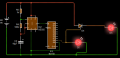
I tried to put an SRC (which I believe is a thyristor) as #12 suggested, it did do it's job and light up LED D3 forever, however, LED D2 (which I want to blink) is also lighting up forever, like in the picture below.

circuit7.PNG
 
Last edited:

Thread Starter

Ayush Modi

Joined Jun 27, 2015
14
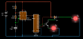
I finally found a solution for making D2 blink and D3 stay by also using a transistor. However, after I connected Q9 to Pin1-Ground (of the 555 timer) so I can make D2 blink once, it created a negative voltage and everything basically got messed up.

circuit8.PNG

Any ideas how to avoid the voltage going negative and having LED D2 only blink once and LED D3 stay on.

Please help
 
Last edited:

GopherT

Joined Nov 23, 2012
8,009
At what rate do you want it to blink? Reasonable options are...

ON/OFF at the rate of the 555 timer (requires an AND gate)
On/Off at 1/2 the rate of the 555 timer (requires an AND gate and FlipFlop)

On for 10 counts of 555 timer then off for 10 count of your original 555 timer (requires a FlipFlop connected to CD4017 Q9 to toggle one LED) and a second 555 timer set up as a one-shot with longer pulse than the first one to keep one LED on).

Also...
What is the collector of your transistor connected to in the image above?

What is limiting current flow to each of your LEDs?
 

Reloadron

Joined Jan 15, 2015
7,977
Your circuit in post #23 has a few problems. The 4017 Decade Counter / Divider sequentially makes 1 of 10 outputs High (Q0 through Q9), the others stay low, in response to clock pulses. You have Q8 directly tied to your supply positive, you can't do that. As before, your Q1 has no base or collector current limiting resistors? Also, per Gopher, where is the collector of Q1 going? Why is the Q9 out of the 4017 tied to common (negative supply)?

<EDIT> Looking at this, is D4 supposed to be an SCR? Looking back at #12's post I think you are trying to use an SCR in there.

Ron
 
Last edited:
Top