 Facebook
 Google
 GitHub
 Linkedin
Hi all!,
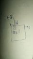
I'm triyng to read light with a MCU. The MCU has OpAmp and 12 bits ADC embidded.
I can vary the "scale" of readings variyng the R/C in parallel. But after a limit, but as the light decreases, there comes a time when I can't read anything no matter how much resistance increases.
I'm assuming it's a uV / lux issue, but the issue is that I can't increase the tension on the OpAmp since it's built into the MCU.
Any idea how to increase the sensitivity in light of this circuit?
Attachments
-
 57.9 KB Views: 21


