Can't read the zeroes in an ASK signal

Thread Starter

aaron_m

Joined Apr 27, 2014
19
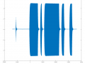
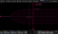
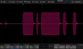
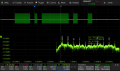
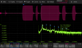
I've captured two signals from a cochlear implant (Cochlear Spectra 22 in this case), operating at a carrier frequency of 2.5 MHz. The first is from the pins to the transcutaneous inductive coil: it's the actual electrical signal sent to the coil. The second is from the coil to a loop of wire connected to the scope probe, so it's kinda what the coil inside my head would see. They're largely similar.

It's supposed to be 6 blocks: sync, active electrode, mode, amplitude, phase 1, and phase 2. You can see the blocks of the packets easily enough. The file format is ofig, which you should be able to open in Matlab, or Octave, so you can zoom in and out.

According to the documentation I can find, the RF data is modulated using ASK. Further, Cochlear Co uses five cycles of RF to represent a 1, where five cycles of no RF indicate a 0. I'm not seeing any difference in heights of the waves, so I'm not sure where the "amplitude" shift keying comes in. I'm also not seeing any blocks of non-RF.

Looking at these waves, what am I missing?

Thanks.
 

Attachments

WBahn

Joined Mar 31, 2012
32,702
Many of us don't have either Octave or MATLAB, so please show what you think the most relevant traces are as screen captures. If we need more, we can figure something out, such as a simple text file with the data values.

Does the implant seem to be working (i.e., does IT seem like it's distinguishing the data bits okay)?
 

WBahn

Joined Mar 31, 2012
32,702
What are the timescales of those two plots? Is the x-axis in seconds on that first one?

Can you provide a link to the documentation that you are referring to?
 

Irving

Joined Jan 30, 2016
4,996
I couldn't open these files in either MATLAB or Octave, neither recognise the file format nor extension. However, looking at the expanded 'scope plot at the cycle level there seems to be no evidence of ASK, FSK or PSK... Can you run a FFT on that, are there any sidebands that might indicate any form of modulation?
 

WBahn

Joined Mar 31, 2012
32,702
Here are some shots from the scope, which give the timebase.

Documentation: https://pmc.ncbi.nlm.nih.gov/articles/PMC2782849/, see section "IV Radio Frequency (RF) Link," particularly "A. Bit Coding," and "B. Frame Coding."
Thanks.

I'm still wondering whether the communication link is actually working or not?

That second image looks like an ASK stream, but at a baud rate of about 80 kbaud instead of the 500 kbaud you are expecting, Is it possible that the implant you are working with just operates at a lower baud rate? I don't know anything about cochlear implants and what the minimum data bit rate is to achieve useful operation.
 

Thread Starter

aaron_m

Joined Apr 27, 2014
19
I couldn't open these files in either MATLAB or Octave, neither recognise the file format nor extension. However, looking at the expanded 'scope plot at the cycle level there seems to be no evidence of ASK, FSK or PSK... Can you run a FFT on that, are there any sidebands that might indicate any form of modulation?
Did you get two files: Spectra22_coil.ofig, and Spectra22_pins.ofig ?
If so, I ran this, and it looks like this on my Mac:
$ file Spectra22_coil.ofig
Spectra22_coil.ofig: Octave binary data (little endian)

Here's an FFT on the pins scope capture, and one for the coil capture, which are essentially identical.
 

Attachments

BobTPH

Joined Jun 5, 2013
11,463
The second screen shot in post #5.

I see a long burst, a short burst, another long, then two short.

You seem to think each burst is a data packet. That is ruled out by the fact, as you noted, that the RF is constant over the bursts.

I believe each burst of RF is a single bit, with the length of the burst determining 1 or 0.

@WBahn hinted at the same in post #7.

Edited to add: It could also be a standard UART protocol, with the first burst being one or two start bits, and the on and off intervals representing bits at a constant rate. It looks like the bit time is about 0.2 divisions or 10 usec, or about 100K baud ASYNC.
 
Last edited:

WBahn

Joined Mar 31, 2012
32,702
The second screen shot in post #5.

I see a long burst, a short burst, another long, then two short.

You seem to think each burst is a data packet. That is ruled out by the fact, as you noted, that the RF is constant over the bursts.

I believe each burst of RF is a single bit, with the length of the burst determining 1 or 0.

@WBahn hinted at the same in post #7.

Edited to add: It could also be a standard UART protocol, with the first burst being one or two start bits, and the on and off intervals representing bits at a constant rate. It looks like the bit time is about 0.2 divisions or 10 usec, or about 100K baud ASYNC.
The document that the TS linked does a very poor job, in my opinion, of describing the protocol (plus, it's unclear if the protocol that is discussed is actually the protocol for the implant the TS is working with). There is information that is hinted at, but missing in details. The physical layer appears more complex than just a succession of bits, each lasting five periods of the carrier. As best I can tell, this protocol is used to communicate with the control/configuration side of the device, but what the TS has captured is the expanded-mode protocol that is used to transmit the run-time data to it in which information is transmitted as a series of five bursts that follow a short sync burst that lasts, at most, seven carrier cycles. The first two data bursts convey a digital number by taking the number, multiplying it by eight and then adding four. That is how many cycles the carrier is broadcast for. The first packet can represent a number between 1 and 22 (inclusive) while the second represents a number between 1 and 30. By multiplying the number by eight, it allows for errors of up to three either direction in the receiver's count while still recovering the correct value. The remaining packets represent larger ranges but don't have the error correction feature because they represent a continuous scale (such as the amplitude of the stimulation) and so errors in count only result in small errors in the effect. The third packet adds 16 to an eight bit value and transmits that many carrier cycles (so 16 to 271, inclusive). The final two bursts have to be the same length and represent the durations of the two phase bursts. The number of cycles ranges between 18 and 3000, with each cycle representing 200 ns of duration (so a range of 3.6 µs to 600 µs). The delay between the end of the third and start of the forth encodes the delay between the two phase bursts and can range from 6 to 50,000 cycles, representing delays of 1.2 µs to 10 ms (so, again, 200 ns per cycle). After the final burst, there is an interframe quiet period that is can last anywhere between 6 and 1.25 million carrier cycles.

Note that these numbers seem to be for a model of the device that has a 5 MHz carrier, so the limits are quite possibly different for the older devices with a 2.5 MHz carrier.
 

BobTPH

Joined Jun 5, 2013
11,463
Wow. That type of encoding is something I have never come across before. I wonder what motivated them to use such a protocol opposed to standard ones.
 

Loreani

Joined Mar 23, 2026
7
I think the confusion is mostly about how the ASK is actually implemented/measured, not that it isn’t there.


From what you describe, this sounds like a form of On-Off Keying (OOK), which is technically a subtype of Amplitude Shift Keying. In OOK, a “1” = carrier present, and a “0” = carrier absent.
 

BobTPH

Joined Jun 5, 2013
11,463
I think the confusion is mostly about how the ASK is actually implemented/measured, not that it isn’t there.


From what you describe, this sounds like a form of On-Off Keying (OOK), which is technically a subtype of Amplitude Shift Keying. In OOK, a “1” = carrier present, and a “0” = carrier absent.
That was what I originally thought, but read @WBahn’s last post. It looks like it is a proprietary protocol where the number of cycles in a burst represents a range of values. Bits are not explicitly represented.
 

WBahn

Joined Mar 31, 2012
32,702
Wow. That type of encoding is something I have never come across before. I wonder what motivated them to use such a protocol opposed to standard ones.
While mostly speculation on my part, it is based on reading between the lines of both that document and other stuff I stumbled across while trying (unsuccessfully) to look at other sources, including one of the patents.

The receiver is powered by harvested power from the RF signal and so has to be extremely low-powered. It also has to fit completely within an in-ear device. So there is not a lot of processing capability available, especially since some of the harvested power must be used to drive the two stimulation coils. So the protocol is designed such that the signal can be, as much as possible, used directly with as little manipulation and processing as possible.

It's pretty amazing, really, that each packet, repeated at just four times a second, might only have 71 cycles and the implant can harvest enough energy from that to maintain itself until the next burst of data.
 

Thread Starter

aaron_m

Joined Apr 27, 2014
19
@WBahn , I think you may be right: it's just a factor of length. I ran a function sweep to generate tones over a range to stimulate multiple electrodes, and captured a whole bunch of packets on the screen. Then I saved the data as Matlab format. Bringing that file to my PC, when I look at them in Matlab / Octave, I can see that the same block per frame - active electrode, for example - is variable: sometimes longer or shorter.

(And, in a personal moment of "duh," my local copy "Cochlear Implants:System Design, Integration and Evaluation" that discusses the "(n-4)/8" is already highlighted. I must've been working on this way later than I should've, and slept right through reading it. But it seemed important, so I highlighted it. shrug)

I uploaded the Matlab file for anyone who's interested to look at. Unzip the file, then run these commands in Matlab or Octave:

load('./SDS814X_HD_Matlab_C2_1.mat');
whos
plot(C2_time, C2_data);

Data file is here:
https://www.dropbox.com/scl/fi/6f8s...ey=2hmsya3f6sks2qxoqhsodek07&st=eysceu31&dl=0
 

Irving

Joined Jan 30, 2016
4,996
Intrigued by this, I wrote a little Octave routine (not used this before, it's sort of C/Java-like so easy to pick up and great for matrix work) to look for +ve maxima in the signal and count them, returning an array of pulse counts, and the start and end index for each group, relative to the start of the dataset .

So
plot(C2_data(5000,7400)) gives:

1774542284960.png

and:

countPulses(C2_data(5000:7400),.5)
ans =

191 2306 105 i.e. starts at 191, ends 2306 and contains 105 cycles.

the second parameter in the call is the level to slice the data at to cancel noise. I didn't see anything in the protocol outlined in post #12 that suggests the amplitude used to discriminate a pulse. However, we know the sync pulse is <=7 cycles, so empirically:

countPulses(C2_data(1:5000),1.4)
ans =

4188 4310 7

and then

plot(C2_data(3500:47000)) gives:

1774551288353.png
and :

countPulses(C2_data(3500:47000),1.4) gives:

ans =

689 811 7
1706 3663 98
4480 5160 34
5976 7414 72
8391 11924 177
14198 17712 177
24214 24337 7
25232 27330 106
28165 28845 34
29662 31100 72
32076 35570 175
37823 41298 175

You can get the delay between the 3rd and 4th chunks from the finish and start counts respectively, ie for the first packet it is 8390-7414 = 976 and for the second its 32076-31100 = 976, both being sampling interval counts, which for this 2.5MHz carrier is 20nS (there are 20 data points per carrier cycle of 400nS), so 976 = 19.52uS though I do wonder about the accuracy of that as there's quite a tail below the sampling level of 1.4

1774553120560.png
 

Attachments

Top