How to measure waterflow sensor to trip alarm

Thread Starter

Super Garball

Joined Sep 11, 2019
10
Hi,

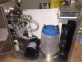
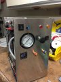
I'm new here and to electronics in general. I've built a Tig welding cooler that takes water from a built in container, pumps it into a Tig torch and then back into a fan cooled radiator and back to the container for recycling. I've added a water flow sensor (ebay:New 1/2'' Water Flow Sensor Control Effect Flowmeter Hall 1-30L/min For Arduino) to the output of the pump. There is a built in power supply for 120vac and 12vDC. I need help with the electronics side of things to finish the project. How do I convert the pulse side of the flow sensor (3 wire) into DC voltage, take readings so that I can have a trigger for low flow to a 12V LED and 12V buzzer? I'd like to be able to adjust the low trigger via some kind of variable resistor.

Thanks in advance for your assistance.
Gary,
 

Attachments

LesJones

Joined Jan 8, 2017
4,174
I think the simplest solution is to use a frequency to voltage converter IC such as an LM2907. You can feed the DC voltage output from this to a comparator chip such as an LM393. You can set the comparator threshold level with a potentiometer so you can set the trigger level. Another method is to trigger a retriggerable monostable from the output pulses. If the trigger pulses occurre more frequently than the timeout value of the monostable then it's output will never go low. If you then follow this with a circuit to detect negative pulses yo can use this to trigger the alarm.

Edit. I have just noticed than AlbertHall has just given you a link to the monostable method.

Les.
 

Thread Starter

Super Garball

Joined Sep 11, 2019
10
A '555 missing pulse detector would do the job. If the input frequency drops below some threshold (can be set by changing the '555 timing resistor) the '555 output will change and could drive an LED and buzzer directly.
https://circuitdigest.com/electronic-circuits/missing-pulse-detector-circuit-diagram
This looks like a great solution I should be able to handle. It appears R2 is the timing resistor that controls the trigger. I have a motor controller connected to the plump which will allow me to manually control flow. I'd like to be able to set a low flow scenario at the pump and then set R2 to trigger. How do I do that with a fixed resistor? Does it make sense to install a variable resistor instead? If so, how do I do that? If what I'm asking doesn't make sense just let me know.
 

Thread Starter

Super Garball

Joined Sep 11, 2019
10
I think the simplest solution is to use a frequency to voltage converter IC such as an LM2907. You can feed the DC voltage output from this to a comparator chip such as an LM393. You can set the comparator threshold level with a potentiometer so you can set the trigger level. Another method is to trigger a retriggerable monostable from the output pulses. If the trigger pulses occurre more frequently than the timeout value of the monostable then it's output will never go low. If you then follow this with a circuit to detect negative pulses yo can use this to trigger the alarm.

Edit. I have just noticed than AlbertHall has just given you a link to the monostable method.

Les.
If for any reason the monostable method doesn't work out for me, I'll try this.
 

AlbertHall

Joined Jun 4, 2014
12,345
R2 and C2 together set the time.
There is a calculator here.
You need to choose values which give a time a little less than the period (1/frequency) of the flow sensor at the flow rate you need a trigger. You should be able to get that from the datasheet for the sensor.

To make it adjustable, you can replace R2 with a variable resistor around double your calculated value to give a reasonable adjustment range. I recommend you add a fixed 1k resistor in series with the variable to protect the transistor if you set the variable resistor to zero.
 

Thread Starter

Super Garball

Joined Sep 11, 2019
10
I think the simplest solution is to use a frequency to voltage converter IC such as an LM2907. You can feed the DC voltage output from this to a comparator chip such as an LM393. You can set the comparator threshold level with a potentiometer so you can set the trigger level. Another method is to trigger a retriggerable monostable from the output pulses. If the trigger pulses occurre more frequently than the timeout value of the monostable then it's output will never go low. If you then follow this with a circuit to detect negative pulses yo can use this to trigger the alarm.

Edit. I have just noticed than AlbertHall has just given you a link to the monostable method.

Les.
Hi Les, Looking at both options here, I may try the LM393/LM2907 first as it appears to I may be able to set a threshold level easier. Can you help with a circuit design? I have no experience in this.
Thanks
 

LesJones

Joined Jan 8, 2017
4,174
Using the monostable method should be just as easy. You just need to make the timing resistor adjustable. I've just been reading trough the thread to see is you have given the frequency of the pulses that you want to detect. (To work out component values.) I did not find it but noticed in your first post the Arduino. If you are using the Arduino in the control system then why not use this to detect the frequency of the pulses.

Les
 

Thread Starter

Super Garball

Joined Sep 11, 2019
10
Using the monostable method should be just as easy. You just need to make the timing resistor adjustable. I've just been reading trough the thread to see is you have given the frequency of the pulses that you want to detect. (To work out component values.) I did not find it but noticed in your first post the Arduino. If you are using the Arduino in the control system then why not use this to detect the frequency of the pulses.

Les
No Arduino here, it’s just in the sensor description on eBay.
 

MrSoftware

Joined Oct 29, 2013
2,188
How frequently do the pulses come from the sensor? The simplest way I can think of is to use a watchdog IC. For example, this one will pull the WDO pin low if it does not receive a pulse within 1.6 seconds. Very simple. If you want to get fancy, you can use the power monitoring feature and signal a separate error if the power to the pump fails.
 

Thread Starter

Super Garball

Joined Sep 11, 2019
10
How frequently do the pulses come from the sensor? The simplest way I can think of is to use a watchdog IC. For example, this one will pull the WDO pin low if it does not receive a pulse within 1.6 seconds. Very simple. If you want to get fancy, you can use the power monitoring feature and signal a separate error if the power to the pump fails.
I have no way of knowing. All I own is a fancy Fluke volt/Hz/current clamp meter.
 

MrSoftware

Joined Oct 29, 2013
2,188
The datasheet for the flow meter should give you some info on how frequently the pulses come for the volume of water you're expecting. I'm almost sure it's going to be faster than every 1.6 seconds.
 

Thread Starter

Super Garball

Joined Sep 11, 2019
10
R2 and C2 together set the time.
There is a calculator here.
You need to choose values which give a time a little less than the period (1/frequency) of the flow sensor at the flow rate you need a trigger. You should be able to get that from the datasheet for the sensor.

To make it adjustable, you can replace R2 with a variable resistor around double your calculated value to give a reasonable adjustment range. I recommend you add a fixed 1k resistor in series with the variable to protect the transistor if you set the variable resistor to zero.
Will a Trimmer pot work? There are 3 legs, instead of the usual 2 on a fixed resistor. How do I wire it up?
 

Thread Starter

Super Garball

Joined Sep 11, 2019
10
Yes, a trimpot is good. Use the middle connection and one of the ends.
Got it. I'm putting a list of parts together including a bread board. This should be fun. It reminds me when I was 12 trying to supercharge my remote control truck with extra batteries. Blew it up. Never told my parents. No internet back then. I'm 50 now.
 

Reloadron

Joined Jan 15, 2015
7,501
I have no way of knowing. All I own is a fancy Fluke volt/Hz/current clamp meter.
OK, back in post #8 Albert gave a link to the sensor we suspect you have. Now if we look at a portion of that data we will see:
  • Flow rate pulse characteristics: Frequency (Hz) = 7.5 * Flow rate (L/min)
  • Pulses per Liter: 450
The pulses per Liter is what we are after and often called The "K" Factor. We know that the flow sensor produces 450 pulses for each liter of volume passing through it. The 7.5 is a result of dividing that 450 by 60 seconds which yields the 7.5.

They are telling us that the Frequency in Hz is equal to 7.5 times the flow rate. This is where you really need to know about what flow rate you expect. Since you don't have a counter or scope to actually view your pulse train for whatever your flow rate actually is.

Years ago I worked with quite a few large scale TIG welding machines which all had water cooled heads. They all just used a simple flow switch in that all we cared about was their either was flow or not and no flow would shut down the system. This would happen if algae or other crud started growing in the cooling reservoir. Anyway, back to what you have.

If I know my absolute minimum flow rate must be 2.5 LPM. Since our flow rate frequency, lets call it Q where Q is the unit for volumetric flow rate, it is in Litres/min. So the frequency for 2.5 LPM would be 7.5 * 2.5 = about 18.75 Hz. Even going back to the 450 pulses our 2.5 Liters would be 1125 pulses and if that happens in 1 min then 1125 / 60 = 18.75 pulses per second which is 18.75 Hz.

I would run my pump at a few speeds and just start and stop flow into a bucket, after 1 min measure how much water is in the bucket. That will give you some idea of what your flow rates are and what is a minimum you need for adequate cooling of the head.

Ron
 
Top