 Facebook
 Google
 GitHub
 Linkedin
Hi forum,
I'm designing a motor controller for a PMDC treadmill motor rated 180V and 2HP. The motor needs to run very smoothly as an accelerometer is connected to it to measure vibration.
The motor housing has an earth lead attached to it's outer casing so I assume it's safe to run it from mains, please tell me if I'm wrong!
I have attached a schematic.
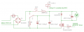
The mains is fused with a 5x20mm glass fuse, F1. Then full bridge rectified with B1. From here the voltage will be around 325Vpp.
When turning ON the motor controller, SW1 is pushed for a second or so to pre-charge the smoothing capacitor C1 and film capacitor C2 through R1. When the voltage reaches a setpoint (which I haven't determined yet) a PIC MCU will switch ON relay K1 to bypass the pre-charge circuit. When the PIC MCU is told to turn OFF, it releases the relay and the capacitors are discharged through R2.
The N-ch MOSFET T1 will be PWM controlled by the PIC MCU through an isolated MOSFET driver. D1 is a flywheel diode for the motor and C3 is a film capacitor to help with the voltage peaks until D1 starts conducting.
Since the motor load can reach 11A (from what I can tell), the DC bus voltage will not be constant, but has a large voltage ripple reaching 110Vpp at full load. To avoid this influencing the motor voltage, and creating torque ripple, I was planning to alter the PWM duty cycle according to the voltage on the DC bus, so the motor will see a constant voltage.
But this, along with the pre-charge circuit, requires me to sample the DC bus voltage. How would you do that and keep isolation to the PIC MCU?
I see 2 options:
1. Use a linear optocoupler. I have not used one before so this is new to me.
2. Use a high voltage linear regulator to feed a small PIC MCU with internal ADC, which measures the voltage from a resistor divider and sends this as digital values through a regular high-speed optocoupler to the PWM MCU.
Regarding isolation, when can you regard a whole circuit as proper isolated? Because some components will have to stay on the mains side. How do you determine which components can stay on the mains side and which should be isolated?
Are there any other reasons to keep certain components isolated than shock hazard?
I'm all in for isolation, and I know it's a hot topic here, I hope my post doesn't break any of the isolation rules here, if it does, I'm very sorry, that was not intended.
Best regards,
Futterama
I'm designing a motor controller for a PMDC treadmill motor rated 180V and 2HP. The motor needs to run very smoothly as an accelerometer is connected to it to measure vibration.
The motor housing has an earth lead attached to it's outer casing so I assume it's safe to run it from mains, please tell me if I'm wrong!
I have attached a schematic.
The mains is fused with a 5x20mm glass fuse, F1. Then full bridge rectified with B1. From here the voltage will be around 325Vpp.
When turning ON the motor controller, SW1 is pushed for a second or so to pre-charge the smoothing capacitor C1 and film capacitor C2 through R1. When the voltage reaches a setpoint (which I haven't determined yet) a PIC MCU will switch ON relay K1 to bypass the pre-charge circuit. When the PIC MCU is told to turn OFF, it releases the relay and the capacitors are discharged through R2.
The N-ch MOSFET T1 will be PWM controlled by the PIC MCU through an isolated MOSFET driver. D1 is a flywheel diode for the motor and C3 is a film capacitor to help with the voltage peaks until D1 starts conducting.
Since the motor load can reach 11A (from what I can tell), the DC bus voltage will not be constant, but has a large voltage ripple reaching 110Vpp at full load. To avoid this influencing the motor voltage, and creating torque ripple, I was planning to alter the PWM duty cycle according to the voltage on the DC bus, so the motor will see a constant voltage.
But this, along with the pre-charge circuit, requires me to sample the DC bus voltage. How would you do that and keep isolation to the PIC MCU?
I see 2 options:
1. Use a linear optocoupler. I have not used one before so this is new to me.
2. Use a high voltage linear regulator to feed a small PIC MCU with internal ADC, which measures the voltage from a resistor divider and sends this as digital values through a regular high-speed optocoupler to the PWM MCU.
Regarding isolation, when can you regard a whole circuit as proper isolated? Because some components will have to stay on the mains side. How do you determine which components can stay on the mains side and which should be isolated?
Are there any other reasons to keep certain components isolated than shock hazard?
I'm all in for isolation, and I know it's a hot topic here, I hope my post doesn't break any of the isolation rules here, if it does, I'm very sorry, that was not intended.
Best regards,
Futterama
Attachments
-
 18.6 KB Views: 16
Last edited:


