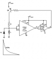
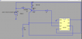
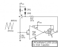
I was thinking power up there would be a low on pins 2&6 the 555 would go high drivingd the second 55 low this would drivethe xstr on startingthe coil High trendinding low
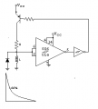
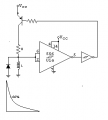
Yes. After paying attention the waveform you sketched, it appears that you want to watch current in the inductor change with time. As the circuit is a the moment, the speed of voltage change across the inductor is limited by the switching speed of the 2M3906, so that would not be the thing to watch. I think what can be done is put the inductor in series with the emitter and switch a fixed voltage across it. That way the collector current will rise nearly linearly with time and it can be observed with a resistor from the collector to ground.
Circuit above will drift with temperature because of the way I limited base voltage.
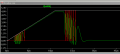
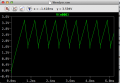
I believe the waveform above is close to what you are looking for.
Looks good.Mostly I was after a LR OSC. WHOSE Freq WILL VARY WITH L .Still fighting the BRAIN fog, but it is getting better. Ilike the linear waveform.
Is the rate of change(slope)on thre triianglewave afuntion of inductance you think?If it is itcoud lfeed a windoe comparitor.Measure the duration and you can have a simple digital read out of inductane just a thought A simple PIC circuit perhaps.
Yes to all of the above. With large inductances the oscillation period is proportional to L. With lower inductances switching speed (of the transistor, I think) contributes a significant error.
This is interesting, I don't temember seeing this done with and inductor before. In some ways it should easier to work with than the LC because the math to solve for L can be simpler.
You know,evenwhen Iwas on top of my game I could not havemade this circuit, Thank you,I have stashed it for posterity.So what do you think the freq equation is?
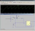
I have been playing with the base resistor R1.
I noticed when the value gets smaller, the spikes will be larger and the speed is higher (R1 = 100 Ohms):
When R1 gets larger, an exponetial signal that is slower will appear (R1 is 100K Ohms):
The formula would look like L = K * period. No squares or square roots needed. (Here "*" indicates multiplication.)
The circuit probably still needs some engineering before it would be useful in a real-world application, as Burtus is showing us. For example, note that the drift in diode voltage with temperature would cause approximately 0.4% drift in frequency per degree.
I was about to ask the same question. But I was under the impression that they're there as a means of dropping the voltage reaching the gate. Though I wouldn't know why.
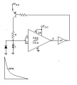
The two diodes establish the votlage across the inductor while the transistor is on. One diode compensates for Vbe and the second one gives the voltage that drops across the inductor.
This second voltage drop is not temperature compensat -a 1.2 V bandgap reference might be a much better choice than the second diode -is there is sufficient voltage and if the bandgap reference is fast enough.
It occurs to me big issue I have been fighting is coil resists change in current. In this case measuring voltage across the coil is wrong headed whilethe R in LR provides an easy way to measure current.The resultant change curve resembles that of a capacitor across the R. Therefore any voltage type sensing should be using the R side if the circuit which is what Dick's circuit does.It only took me several years to get this down. I feel pretty stupid some times
Well, this thread has been going a while. But I do not see the problem with Wendy's original proposal to measure the inductance. If Vt is the applied voltage and V1 the voltage across the inductor, the current flow is (Vt-V1)/R1. Once you know the current, you can determine the impedance. Then measure the resistance at D.C. and extract the inductance. No need for complicated circuitry, only a well calibrated A.C. source and voltmeter. Remember, though, to measure the current accurately you have to measure the voltage across resistor R1 directly (that is across R1 as a differential). As there is no phase shift in R1, what you see is what you get, but you cannot just subtract V1 (measured to ground) from Vt as that will have a phase shift. What works reasonably well is to keep the current fairly low so that the voltage drop across R1 is high: then the current will be approximately (Vt-V1)/R1 as measured to ground, but that depends on how sensitive a voltmeter you have. (Or how much current you can push out from the AC source)
If I were to use IC's I would use them to amplify the voltage measured.

 Facebook
 Google
 GitHub
 Linkedin