How to measure an inductance

Thread Starter

Wendy

Joined Mar 24, 2008
23,869
We have
\(
\frac{V_o}{V_i}=\frac{j\omega L}{R_1+j\omega L}
\)

you are measuring
\(
\alpha = \left|\frac{V_i}{V_o}\right|
\)

so

\(
\frac{1}{\alpha^2} = \left|\frac{V_o}{V_i}\right|^2= \frac{\omega^2 L^2}{R_1^2+\omega^2 L^2}
\)

which simplifies to

\(
L = \frac{R_1}{\omega\sqrt{\alpha^2-1}}
\)

for your example where R1=180, Vi=30.4mV, Vo=15mV, and freq = 100kHz you get L=163uH.
Some of that math does not look quite right. If you catch the 1st 10 or so posts you'll see we went through a lot of that.

The core equation that is a given is:

Z = SQR (XL²+R1²)

You have the statement, Vo/Vi = jωL / (R1 + jωL)

I don't see that as a given. Where did you derive that from?

Another thing you could do is to measure the voltage across the R1 resistor directly, then find the resistance that gives the same voltage across R1 when the new resistance replaces the inductor - that resistance will be the impedance of the inductor at 100 kHz.
If you check the early problem on post #11 you'll find the values are pretty close to what you describe. My original setup was a variable resistor, I went to a fixed resistor to eliminate as many variables as I could.

To Bertus:

Remember, the goal is minimum test equipment and parts. Oddly enough, I have a capacitance box I paid a $1 for at a flea market (I go to a lot of HAM flea markets). I'm trying to come up with something a noob can duplicate with a minimum of fuss.


As soon as I get a chance I'll change the experiment a little, (1) add a transistor buffer, (2) and as a separate experiment, drop the freq to 10Khz.
 
Last edited:
Tesla23

Joined May 10, 2009
560
Some of that math does not look quite right. If you catch the 1st 10 or so posts you'll see we went through a lot of that.

The core equation that is a given is:

Z = SQR (XL²+R1²)

You have the statement, Vo/Vi = jωL / (R1 + jωL)

I don't see that as a given. Where did you derive that from?


If you check the early problem on post #11 you'll find the values are pretty close to what you describe. My original setup was a variable resistor, I went to a fixed resistor to eliminate as many variables as I could.
\(
\frac{V_o}{V_i}=\frac{j\omega L}{R_1+j\omega L}
\)

is a voltage divider, saying that Vo/Vi is the impedance of L (jwL) divided by the total impedance (R+jwL).

If you look at your analysis of post#11

Vin = 30.4mv RMS
Vout =15.0mv RMS
I = 86.9µa
Z = 350Ω
XL = 301.8
L = 480µH

this can't be right as \(\left|\frac{X_L}{Z}\right|\) should be about 0.5 (15.0/30.4). My answer has XL=102 and Z=207.

If you want to do it with trigonometry:

\(Z^2=R_1^2+X_L^2\)

and for the voltage divider:

\(\frac{X_L^2}{Z^2}=\frac{V_o^2}{V_i^2}\)

which if you solve you get

\(X_L^2=\frac{R_1^2}{\frac{V_i}{V_o}^2-1}\)

which is the same expression as I posted


To Alberto, I think you have Vo across R not across L as I understand the diagram.
 

Tesla23

Joined May 10, 2009
560
I think your equation breaks down in the linear addition of R1+XL, XL being the ωL part of the equation.

If you run your solution through it doesn't pass the math check.
What math check does it fail?

Here (http://en.wikipedia.org/wiki/RL_circuit) is another explanation that may help, but the notation is a bit cumbersome.

Here is another statement of the transfer function:
http://qbx6.ltu.edu/s_schneider/physlets/main/rlc_highpass.shtml

and whilst trying to find you an alternative explanation I came across one of the most useless applets I have seen for a while:
http://www.falstad.com/circuit/e-filt-hipass-l.html
 

Thread Starter

Wendy

Joined Mar 24, 2008
23,869
Sorry, I want to do some checks, so I deleted my arguements. I'll get back when I have my act together a bit more.

But find the flaw in my methology, if you can.
 

Thread Starter

Wendy

Joined Mar 24, 2008
23,869
OK, here is the problem I'm having with your math...

\(
\frac{V_o}{V_i}=\frac{j\omega L}{R_1+j\omega L}
\)

is a voltage divider, saying that Vo/Vi is the impedance of L (jwL) divided by the total impedance (R+jwL).
R1+jωL is not the Z of the circuit. It breaks down from there.

I tried figuring the current using your answer, I = 147µa. That means the voltage drop across R1 is 26.5mv, another check bust. The voltage across the coil is right though, 15mv.

I appriciate your input though, I went through a lot of that when I started this.

I'm a zombie when I get home from work, so I'm going to bed.
 
Last edited:
One problem I see with your method is that you're assuming the inductance is a pure inductance.

I wound up an inductor on a bolt similar to what you show in post #12.

I then measured its impedance at frequencies from 20 Hz to 1 MHz.

Its DC resistance is .37Ω.

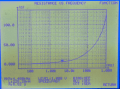
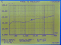
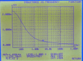
The attachments show plots of its inductance, its AC resistance, and the phase angle of its impedance. Notice that the AC resistance (the Equivalent Series Resistance) is much greater than the DC resistance.

At 20 Hz the inductance is greater than 2 mH and at 100 kHz the inductance is 75.5μH.

But the real kicker is shown by the phase angle plot. The phase angle of the inductor's impedance is between 40° and 60° over the whole range from 30 Hz to 100 kHz. This means that the Equivalent Series Resistance of the inductor is about equal to its reactance at all those frequencies.

Using a bolt for an inductor core gives a poor inductor. Solid conducting material for an inductor core causes the inductance to decrease with increasing frequency, drastically as you can see. That's why good inductors have a ferrite or powdered iron core, or a stack of laminated silicon steel sheets.

So, you need to keep the resistance RL that you showed in the figure in post #1, especially for your inductor wound on the bolt.

Finally, if you assume the inductor is a pure inductance (no series resistance) then you can determine the inductance with only two measurements (Vr and Vo in post #6), but if the inductance has significant series resistance then it will take more than two measurements.

This is because the magnitude of the impedance of an inductor with some series resistance can occur more than one way. For example, imagine you had an inductor with 5 ohms impedance magnitude. That impedance magnitude could be due to an inductive reactance of 3Ω and a resistance of 4Ω, or it could be due to an inductive reactance of 4Ω and a resistance of 3Ω. You can't tell the difference by just measuring the magnitude of the impedance; you need its phase angle as well. In fact, that 5Ω impedance magnitude can be due to an infinite number of combinations of reactance and resistance.

When you measure Vo in post #6, you are only measuring the magnitude of the impedance of the inductor. You also need to know the phase angle if you want to determine the inductance part of the impedance.
 

Attachments

Thread Starter

Wendy

Joined Mar 24, 2008
23,869
Graph #2 is showing a rather large increase in internatal resistance, from near 0Ω to almost 120Ω near 1MHz, at 100KHz it was 30Ω. What would cause such an increase, do you think? Skin effect for such low frequencies doesn't seem very likely.

The part works at 70Khz as good as an off the shelf model, my flyback LED flasher is what got me started on this. The measured inductance is almost the same as the off the shelf model I'm comparing it to, which is what I was designing for. The off the shelf is a choke, this could make the a difference, since it isn't really designed to be constant across the board. Also, the apparent inductance increased, though this could be an artifact.

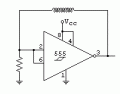
I'm thinking of some alternate methods, such as a 555 inductive hysteretic oscillator. It will useful to run several checks, since the base oscillation is totally dependent on LR charge curve, the other major method of measuring inductance, and since varing the resistor by one or two magnitudes will also do the same for the frequency.
 
Graph #2 is showing a rather large increase in internatal resistance, from near 0Ω to almost 120Ω near 1MHz, at 100KHz it was 30Ω. What would cause such an increase, do you think? Skin effect for such low frequencies doesn't seem very likely.
Because when you use a solid piece of metal for the core it acts like a shorted turn on the inductor. Iron is not only magnetic, it's a reasonably good conductor of electricity.

That's why you want to break up the core into small pieces that are insulated from each other so they don't form a complete conductive circuit, like powdered iron or ferrite or laminations.
 

Tesla23

Joined May 10, 2009
560
OK, here is the problem I'm having with your math...


R1+jωL is not the Z of the circuit. It breaks down from there.

I tried figuring the current using your answer, I = 147µa. That means the voltage drop across R1 is 26.5mv, another check bust. The voltage across the coil is right though, 15mv.

I appriciate your input though, I went through a lot of that when I started this.

I'm a zombie when I get home from work, so I'm going to bed.
if the loss in your inductor is insignificant then

\(V_L^2+V_R^2 = V_i^2\)

and so the voltage across R1 must be about 26mV. If

\(V_L^2+V_R^2 \neq V_i^2\)

then the loss in your inductance is significant (as suggested by The Electrician).

What do you mean by "R1+jωL is not the Z of the circuit", how do you work out the impedance of a resistor and inductor in series?
 

Thread Starter

Wendy

Joined Mar 24, 2008
23,869
Z is the square root of the squares added. You left the square root out. It is not straight addition.

There has got to be something not kosher with my setup, either my meter isn't flat, or something. I ran another experiment with 1Khz, 10Khz, 100Khz. The numbers are all over the map.

I'm assuming the resistance stays 177.3Ω.

Bolt Coil
. Hz ........ Vi ......... Vo
1Khz ..... 949mv ... 523mv
10Khz ... 732mv ... 143.1mv
100Khz . 30.7mv ... 15.4 mv

Time for a different approach, I think.
 
Last edited:

eblc1388

Joined Nov 28, 2008
1,542
To acts as a sanity check for my inductance meter & measurement, I have an air coil made with some 50~70 turns AWG#26 on a 2.5" PVC pipe section.

I trimmed the number of turns so that it measures about 195uH on the 0~200uH meter range. I carefully label the inductance on it and it has served me well for many many years.

I'm sure there is a webpage somewhere showing inductance calculation of an air core inductor with specific dimension. Builds one now and avoid going insane.
 

Tesla23

Joined May 10, 2009
560
Z is the square root of the squares added. You left the square root out. It is not straight addition.
I was using complex impedances (note the 'j'). See http://en.wikipedia.org/wiki/Electrical_impedance

The impedance of R in series with L is:

\(Z = R + j \omega L\)

which has magnitude:

\(|Z| = \sqrt{R^2 + \omega^2 L^2}\)

Time for a different approach, I think.
Why not simply use a few plastic capacitors say 1n to 100n, and see what resonates around 100kHz. (11.5nF should resonate with 220u at 100kHz). Fix C, use a series LC circuit with your series R1, simply adjust the frequency to find the minimum voltage across the series LC. The value of C and the resonant frequency will give you L.

\(L=\frac{1}{\omega^2 C}\)

where ω is the resonant frequency.

You can even use your R1 and the voltages Vo and Vi to measure the series loss resistance of the inductor (which will be all that is left once you have cancelled out the inductive reactance at resonance).
 

Thread Starter

Wendy

Joined Mar 24, 2008
23,869
The point has been made (and I tend to believe it) is that an inductor using mild steel isn't too stable across the band. I was hoping that it would be OK for the relatively narrow range up to 100KHz, but this doesn't seem to be the case. I might revisit this subject, I tend to work on projects, then move on and come back later.

The inductive 555 hysteresis oscillator should prove how stable this inductor is, one way or another. I'll show the schematic of what I'm talking about tomorrow.
 
I measured (with an LCR meter @ 1 kHz) the inductor on a bolt I wound and its inductance is 444.8μH. Measured another way, as an impedance, Z = RL + jXL, RL=2.95Ω and XL = 2.79Ω.

I connected the inductor in series with R1, a 3Ω precision resistor, and applied a 1kHz signal to the series combination as in post #1.

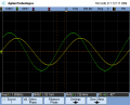
I measured the voltage across the 3Ω resistor and across the inductor separately with a scope. The result is shown in the first image below. The measurements of frequency, voltage of each trace and phase angle can be seen at the bottom of the screen.

The voltage across the resistor R1 is the yellow trace (92.7< -42° mV) and the voltage across the inductor is the green trace (129.4 mV ). Inductor current lags voltage, and the yellow trace is voltage across R1 which is also proportional to current through the inductor.

We can solve for the inductance by noting that (with Vr and Vo as in post #6, but with the difference that L includes a series resistor, RL):

Vo/Vr = I*(RL + jωL)/(I*R1) = (129.4 )/(92.7< -42°) = 129.4/(68.89 - j62.028) = (1.0374 + j.93404)

where the < symbol means "at an angle of" and jωL = XL. We see that the phase of the inductor current lags behind the inductor voltage by an angle of -42°. We know this because the inductor current is the same as the current in R1, and the voltage across R1 is in phase with the current through R1 (which is the same as the inductor current). We need this information to solve for L.

Having converted to rectangular coordinates to carry out the arithmetic, we have

(RL + XL) = R1 * (1.0374 +j.93405) = 3.11 + j2.80

This compares well to the value measured on an LCR meter given above of 2.95 + j2.79. Knowing that jωL = 2.79, we can calculate L = 2.80/(2*pi*1000) = 445.6μH, very good agreement with the LCR meter measured value of 444.8μH. The resistive component of the inductor's impedance is 3.11Ω which compares favorably with the LCR meter value of 2.95Ω

Since the measurement was made with a scope, the phase information was easy to get, which wouldn't be possible if just a DVM was used to measure the voltages Vr and Vo.

A simple phase meter could be built using 2 comparators to square up the sine wave voltages Vr and Vo, passing the comparator outputs into an exclusive or gate phase detector. That way the use of a scope could be avoided, but the all-important phase information could still be obtained.

As an alternative, an second set of measurements could be made after connecting a capacitor across the inductor. This way we would have enough measurements to solve for all our unknowns even though we don't know the phase relationship between the inductor voltage and inductor current.

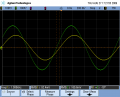
The second image shows the results after connecting a 14.93 μF capacitor across the inductor. From both sets of measurements, using just the magnitude of the various voltages, the inductance can be calculated without ambiguity.
 

Attachments

Thread Starter

Wendy

Joined Mar 24, 2008
23,869
OK, another thought occurs. It revolves around this...


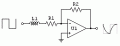
We have converted the classic LR charge curve into a voltage. This gives me something to work with.
 

Attachments

Last edited:

Thread Starter

Wendy

Joined Mar 24, 2008
23,869
I tried breadboarding this,


It was a total flop. I have some serious thinking to do.
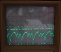
Back to and oldie but floppie. I used a 220µH coil and a 330Ω resistor and got this wave form...


It gets even weirder with other values, not even close to theory. I'm using two 0.1µF decoupling caps on both rails of the protoboard. My new oscope is going to let me look at things the old HP couldn't touch.

I'm looking for suggestions.
 

Attachments

Last edited:

Ghar

Joined Mar 8, 2010
655
Personally I do it by using an RL low pass filter and finding the 3dB frequency. I'm surprised no one brought this up...

Put in a 1V sinusoid and sweep frequency until you hit 0.707V across the resistor.
\(L = \frac{R}{2\Pi f}\)

If you use a larger resistor in the several kohm range you will dwarf all coil resistance etc. and the frequency should stay reasonably low.

Though, it would still fall apart I guess in The Electrician's scenario of a super lossy inductor.
 
Top