How To Make Dc Power Supply ?

Thread Starter

abhimanyu143

Joined Aug 25, 2014
211
After some reading I have made this calculation
component
transformer
diode rectifier
filter capacitor
R load

1. transformer
primary voltage Vp= 230 Vrms ac
secondary voltage Vs= ?
primary turns Ns = 5
secondary turns Np= 1
primary current Ip =?
secondary current Is ?
R load = 50 ohms
formula for transformer
Vp/Vs=Ip/Is=Np/Ns

secondary voltage

Vp/Vs= Np/NS

230/Vs=5/1

Vs = 46V rms Ac

secondary current


Is =Vs/Rload

Is= 46/50= 0.92 amp rms Ac

primary current


Vp/Vs=Is/Ip
230/46=0.92/Ip

Ip= 0.184 amp rms AC

transformer with load

primary voltage Vp= 230 RMS ac
secondary voltage Vs= 46 volt Rms Ac
primary turns Ns = 5
secondary turns Np= 1
primary current Ip = 0.184 A rms Ac
secondary current Is = 0.92 A rms Ac
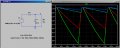
2.rectifier
If we connect single rectifier diode then

We know following for rectifier

Input voltage = 46 Vrms Ac

Input current =0.92 Arms Ac

I have to find out output voltage, current for rectifier


Output current for rectifier


Idc= Vs/RL= (46-0.7)/50=0.906 dc


Output voltage

Vdc = Idc* Rload=0.906*50= 45.3 vdc
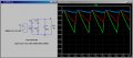
3.filter capacitor
now we know input voltage and current for capacitor
Idc= 0.906 dc
Vdc =45.3 vdc

I want to do some calculation for capacitance
how to choose capacitor value ?


Last edited:

#12

Joined Nov 30, 2010
18,224
Sqrt2 C Er F = I where Er is the allowable, peak to peak ripple voltage, F is the frequency after whichever rectifier design you used, C = capacitance, and I = current to the load.
 

Thread Starter

abhimanyu143

Joined Aug 25, 2014
211
Sqrt2 C Er F = I where Er is the allowable, peak to peak ripple voltage, F is the frequency after whichever rectifier design you used, C = capacitance, and I = current to the load.
I know only frequency 60 Hz and load current Idc= 0.906 dc
how to determine peak to peak ripple voltage ?
 

#12

Joined Nov 30, 2010
18,224
I know only frequency 60 Hz and load current Idc= 0.906 dc
how to determine peak to peak ripple voltage ?
Use the math I gave you. sqrt2 = 1.414 60 Hz = F if you didn't use a full wave rectifier. It's 120 Hz if you did. Either you decide the ripple voltage you want to allow or you decide the capacitor size. The answer comes out of using the formula.
 

MikeML

Joined Oct 2, 2009
5,444
The first figure might help you understand the peak voltage that the filter capacitor charges to, and how the value of the filter capacitor effects the ripple. The second figure shows why it is better to use a full-wave rectifier...
 

Attachments

Last edited:

MaxHeadRoom

Joined Jul 18, 2013
28,686
He is telling you that the RMS voltage of a sine wave will reach a DC peak of 1.414 times the RMS value after it is rectified (minus the voltage lost in the diodes).
...And if you want 46vdc as a final result, that would be 46vdc X 0.707 = 35vac required.
Max.
 

cl10Greg

Joined Jan 28, 2010
67
I am not sure how set in your design you are, but have you looked at any of the various power supply designer web tools? TI has one, Fairchild, Power integrations, etc...
 

Thread Starter

abhimanyu143

Joined Aug 25, 2014
211
primary voltage Vp = 230 v ac
peak voltage of secondary=65.004 V Ac
Rms voltage of secondary = 46 V ac
output of rectifier = 65.044-0.7=64.344 V ac
main frequency F= 60 Hz
load current Idc= 0.906 dc
peak to peak ripple voltage Vr= 2 v

using formula for capacitance

C=I load /2*F*Vr
C=0.906/2*60*2
C=0.906/240

C=0.003775 F
 

Thread Starter

abhimanyu143

Joined Aug 25, 2014
211
If my capacitance value is correct then I want to add regulator Ic
how to do some calculation for regulator Ic ?
 
Last edited:

#12

Joined Nov 30, 2010
18,224
C = Iload /1.414 * F *2
C = .906/1.414 * F * 2
C = 53388 uf

Read the datasheet for the regulator you want. It tells all about which capacitors to use and how to adjust for different output voltages. They are often a little different from brand to brand, so pick one and read about it. Small capacitors are used to keep the regulators from oscillating. Your big capacitor is finished.
 

Thread Starter

abhimanyu143

Joined Aug 25, 2014
211
C = Iload /1.414 * F *2
C = .906/1.414 * F * 2
C = 53388 uf

Read the datasheet for the regulator you want. It tells all about which capacitors to use and how to adjust for different output voltages. They are often a little different from brand to brand, so pick one and read about it. Small capacitors are used to keep the regulators from oscillating. Your big capacitor is finished.
what is 1.414 ? C=I load /2*F*Vr Is it wrong ?
If I connect regulator I think I need 2 small capacitor
 

#12

Joined Nov 30, 2010
18,224
On page 8, that PDF goes right into talking about Vpeak, but I can't find where it explains that Vpeak = the square root of 2 times the RMS value of the voltage. Transformers are usually labeled in RMS voltages. ps, the square root of 2 is 1.4142136 according to my calculator.
 
Top