Facebook
 Google
 GitHub
 Linkedin
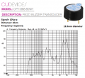
Around 60 decibels, is that loud for a small speaker?I suggest using a chip recorder like a surface mount ISD1610, wouldn't need a micro. How loud does it need to be?
How to make a -very- small button/speaker circuit?
- Thread starter CocoaHere
- Start date