help with reducing consumption for very small motor / low voltage buck

Thread Starter

ludovic_pommier

Joined Jan 10, 2012
23
Hi,

I'm trying to get a small dc motor to run for the longest possible time from the energy of a small solar panel with a liion battery (or cap). The solar panel output up to 40mA at 0.5v (close to max max power point). I have tested the motor, it starts at 0.142v/11mA (I can also do 24mA and 270mV).

I'm using a bq25570 energy harvester on a board from aliexpress bq25570 module
It's basically dealing with the battery management, energy harvesting and outputting 2.6v (100mA max).

I want the motor to run as slowly as possible to reduce it's power consumption. So, I have 2.6v and need to reduce it to approx 0.2. I could not find a suitable buck (I'm trying to avoid smd component so can't use something like ADP5331 and anyway, it's still cannot go under 0.8v).

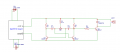
I have tried an astable multivibrator to PWM the motor and reduce its power consumption. It's working fine to reduce the motor speed and I can get it down to 11mA and 142mv, but the problem is that the circuit consumes 11mA at 2.6v! 11 mA are going through Q3 with 142mV for the motor and the rest between Q3 and ground (about 2.56V*11mA). I have tried playing with capacitor and diode, but can't solve it. From my readings, it seems I may need to add an inductor somewhere??
Or should I feed back the excess voltage inside the BQ2550 (connecting emitter of Q3 and ground to + and - of solar cell, but then I'll have to add a diode on the solar cell, possible but not sure it would work and don't really want the voltage drop of the diode + it may mess up the MPPT of the BQ25570).

Thanks in advance for any suggestion, either:
- on the overall idea of BQ25570 + SOLAR + BUCK / PWM + LIION BATT + DC MOTOR
- on how to reduce the power consumption of the multivibrator (kind of turning it into a buck?)
- on what other solutions to efficiently reduce motor consumption with through hole if poss)
- on any good low voltage buck on a board or SMD if nothing else
 

Attachments

panic mode

Joined Oct 10, 2011
4,864
hmmm... if just modifying what you have, i'd say increase resistor values, probably R1=R2=3.9k to 10k. that should bring idle current down.
increase potentiometer value to say 250k. and don't let Q1 current go to waste, capture it and drive Q3 with it.
this would get you pulses peaking at some 30-50mA but by lowering duty cycle should be able to bring the average current value down.
there are also various micropower DCDC regulators like LTC38xx but may not work below 2.75V or so.


1727225186580.png
 
Last edited:

Thread Starter

ludovic_pommier

Joined Jan 10, 2012
23
hmmm... if just modifying what you have, i'd say increase resistor values, probably R1=R2=3.9k to 10k. that should bring idle current down.
increase potentiometer value to say 250k. and don't let Q1 current go to waste, capture it and drive Q3 with it.
this would get you pulses peaking at some 30-50mA but by lowering duty cycle should be able to bring the average current value down.
there are also various micropower DCDC regulators like LTC38xx but may not work below 2.75V or so.


View attachment 332338
Thanks. I have tried with higher R1 and R2 and with 2.7k, it wasn't working, Q1 wasn't switching on. So I would need to also increase the pot to be able to increase R1 and R2?
Just one thing, I'm interested in increasing the efficiency. For now, input=2.6V*11mA and output = 142mV*11mA, efficiency is 5%. Any thoughts?
 

crutschow

Joined Mar 14, 2008
38,316
he circuit consumes 11mA at 2.6v! 11 mA are going through Q3 with 142mV for the motor and the rest between Q3 and ground (about 2.56V*11mA)
How are you measuring that current?

The average (not peak) current through Q3 should be a fraction of 11mA.
But note that the drop across D1 is about 0.7V, so it will be dissipate most of the power with a PWM drive, not the motor, since the diode is carrying the motor current when the PWM is off.
A Schottky diode would cut that loss at least in half.
 

Thread Starter

ludovic_pommier

Joined Jan 10, 2012
23
How are you measuring that current?

The average (not peak) current through Q3 should be a fraction of 11mA.
But note that the drop across D1 is about 0.7V, so it will be dissipate most of the power with a PWM drive, not the motor, since the diode is carrying the motor current when the PWM is off.
A Schottky diode would cut that loss at least in half.
thanks for the reply. I've only measured current at the input (where I feed the 2.6v and I read 15mA - 4ma seems to be the circuit consumption with no load, so discounting it and taking 11mA) and output (the motor with 11mA and 142mw), so maybe (probably) there is no current between emitter of q3 and ground. But still left with an efficiency of 5% or am I very confused? where do the 2458mv*11mA=27mW go?
 

Thread Starter

ludovic_pommier

Joined Jan 10, 2012
23
thanks for the reply. I've only measured current at the input (where I feed the 2.6v and I read 15mA - 4ma seems to be the circuit consumption with no load, so discounting it and taking 11mA) and output (the motor with 11mA and 142mw), so maybe (probably) there is no current between emitter of q3 and ground. But still left with an efficiency of 5% or am I very confused? where do the 2458mv*11mA=27mW go?
sorry didn't read all. I used the diode for the back emf of the motor. Is it where the power goes? If so, can I do without (I'll put a shotky for a start)?
 
This multivibrator needs to not oversaturate the transistors to begin oscillate.
So if Rc is 4k7 the Rb has to be 220k at least (considering Beta about 100).

If the transistors have a huge Beta (like 300) the difference between Rc and Rb should be even more.

Btw, there exists a Pnp+Npn multivibrator which has lower power consumption, because in Npn+Npn a one of transistor is always conducting.

Also the Npn+Npn is more suitable for symmetrical drive (50% duty). You need about 10% duty that is more suitable for Pnp+Npn.
 
Last edited:

crutschow

Joined Mar 14, 2008
38,316
Is it where the power goes? If so, can I do without (I'll put a shotky for a start)?
The diode is needed to carry the motor current when Q3 is OFF, so can't be eliminated.
A Schottky diode will reduce the loss during that off time.

For maximum efficiency you could add MOSFET across the motor to conduct the motor current for minimum voltage drop, but that requires a control signal to turn the MOSFET ON only when Q3 is OFF.
 

Thread Starter

ludovic_pommier

Joined Jan 10, 2012
23
I meant what instrument did you use for the measurement?
just a good digital multimeter at both motor and overall input. Guess maybe I did not get any potential voltage spikes, but just measured avg voltage then. Anyhow did a lot of test with the suggestions received (thanks everybody):
- removed the diode: no change in power consumption
- increased the frequency by changing capacitor: maybe 2mA of overall consumption gained.
As said by many, it seems I'm feeding too much to the transistors, so tomorrow building with mosfet (got FQP30N06L) or seriously reducing the resistors if keeping with BC547 as now at least for the output transistor and maybe for the whole oscillator. Will also try the combo PNP+NPN.
 

Thread Starter

ludovic_pommier

Joined Jan 10, 2012
23
The diode is needed to carry the motor current when Q3 is OFF, so can't be eliminated.
A Schottky diode will reduce the loss during that off time.

For maximum efficiency you could add MOSFET across the motor to conduct the motor current for minimum voltage drop, but that requires a control signal to turn the MOSFET ON only when Q3 is OFF.
I've read about using a mosfet as a protection for a motor and will also give that a go.

Can't really figure out how to replace Q3 by a fqp30n06l as not sure how to get the required 2v out of Q1 (maybe decreasing r2? and r3 for Q2)?
 

crutschow

Joined Mar 14, 2008
38,316
how to replace Q3 by a fqp30n06l as not sure how to get the required 2v out of Q1
Ground Q1s emitter and take the voltage from the collector.
I've read about using a mosfet as a protection for a motor
Below is the LTspice sim of an example circuit using a P-MOSFET is place of a diode across the motor to carry the current when the PWM signal is off:
Note that the voltage across the MOSFET is <10mV (yellow trace notation) when carrying the motor current (red trace) , much less than the 0.3V-0.4V a Schottky diode would have.

The MOSFET must be a logic-level type with a Vgs threshold of ≤1V maximum.

1727318187621.png
 

Sensacell

Joined Jun 19, 2012
3,768
Ground Q1s emitter and take the voltage from the collector.
Below is the LTspice sim of an example circuit using a P-MOSFET is place of a diode across the motor to carry the current when the PWM signal is off:
Note that the voltage across the MOSFET is <10mV (yellow trace notation) when carrying the motor current (red trace) , much less than the 0.3V-0.4V a Schottky diode would have.

The MOSFET must be a logic-level type with a Vgs threshold of ≤1V maximum.

View attachment 332418

Very clever circuit!

Needs to be driven with a fast edges to minimize the nasty shoot-through current when the input voltage transitions between high and low- when both transistors conduct at the same time.
 
You can try something this with mosfet switch.
Use 20mA Bjts if possible with Beta 70-150 (no more).
A 100mA types will be good also.

Don’t go higher in frequency than about 500Hz since the mosfet turns off slowly (because of gate discharging just thru 4k7 resistor), so it will be in linear region too much time, i.e. will cause a lot of waist.

The duty cycle (output voltage) is set with R3:R4 and R5:R6 ratio.
Both sides should be the same, symetrical.
Frequency is set mainly with capacitors, the resistors doesn’t give you much variability.

A current through motor (R7):
IMG_1063.jpeg
Use a logic level mosfet with low Vth.
Bjt switch (instead mosfet) can be used also like 2n2222 with 4k7 in base.
 
Last edited:
If you want to increase the switching frequency you need to add a Q3 that ensures a fast mosfet gate discharging.

The Q3 is conducting for a very small time only when collector of Q2 is falling to Gnd, just enough to discharge the gate. This time is set with C3 value.

All others stay the same.
Then you can go up to few kHz.

IMG_1065.jpeg
 
Last edited:

MisterBill2

Joined Jan 23, 2018
27,164
Quite an interesting conversation.
Normally, motor speed is determined by the application, and so I wonder what sort of application can utilize a motor speed "As slow as possible". The voltages and currents mentioned in post #1 are indeed very low for a motor doing anything useful.
So here might be an alternative scheme available if the application were better understood.
 

Thread Starter

ludovic_pommier

Joined Jan 10, 2012
23
Quite an interesting conversation.
Normally, motor speed is determined by the application, and so I wonder what sort of application can utilize a motor speed "As slow as possible". The voltages and currents mentioned in post #1 are indeed very low for a motor doing anything useful.
So here might be an alternative scheme available if the application were better understood.
Hi,
the motor is animating the propeller of a model plane (no load at all except a 4cm well balanced plastic propeller weighting a few grams).
cheers
 
Top