How to log 2 different rotating movements

Søren

Joined Sep 2, 2006
472
I again tried to open it and i got my camera lens between the left and right side of the case so i got some kind of pictures.
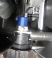
Hard to see what goes on from those angles, but definitely a start :)

Does the blue part move in/out when you turn the knob (a speed marker and a flash light may be helpful)?


If so, the distance it moves may be used.
It seems that there's a cable going to the top of the blue piece - does it go to the speedometer output or some tensioner?
Can you see anything at all moving when you twist the knob?
 

Attachments

Thread Starter

susannah

Joined Feb 14, 2010
87
Blue part don't move at all. It looks like some kind of sensor and all he moving parts are inside it.

Cable goes under spinning wheel so i can't see where it goes. When i twist the knob, nothing moves.
 

Thread Starter

susannah

Joined Feb 14, 2010
87
I can't get software oscilloscope working, but if i hook it up to one of the Arduino digital pins then pin gets hot once per revolution. So the signal is digital not analog?
 

Reloadron

Joined Jan 15, 2015
7,517
I can't get software oscilloscope working, but if i hook it up to one of the Arduino digital pins then pin gets hot once per revolution. So the signal is digital not analog?
Yes, my guess would be digital pulses. While I can appreciate your enthusiasm, unless we know what a signal is and looks like it is unwise to connect it to an Arduino or anything. We need a method to see what you have.

Ron
 

Thread Starter

susannah

Joined Feb 14, 2010
87
Yes, my guess would be digital pulses. While I can appreciate your enthusiasm, unless we know what a signal is and looks like it is unwise to connect it to an Arduino or anything. We need a method to see what you have.
Does any of these do the job? I been thinking buying one of these.

SCANALOGIC is propably better? I have no idea which one is best.

SCANALOGIC-2 PRO
http://www.ikalogic.com/ikalogic-products/scanalogic-2/
http://www.lipoly.de/index.php?main_page=product_info&products_id=162653

24Mhz 8 Channel Logic analyzer
https://www.saleae.com/
http://www.lipoly.de/index.php?main_page=product_info&products_id=218104
 

Reloadron

Joined Jan 15, 2015
7,517
I don't think you really need a logic analyzer. Let's try something. Awhile back you wrote:

Good news guys. The display can be removed and it is connected to bike with 2 wire cable and once per revolution bike sends some kind of pulse! There must be some kind of button which is closed once a turn.

I used generic multi meter and turned multi meter setting to 2000k Ω. When i rotate bike crank one full circle, number 1 in multi meter screen turns to much bigger number.
Try that again but set the meter for DC Volts rather than resistance. Slowly rotate the wheel and let's see what that output does.

Ron
 

Thread Starter

susannah

Joined Feb 14, 2010
87
I don't think you really need a logic analyzer. Let's try something. Awhile back you wrote:

Try that again but set the meter for DC Volts rather than resistance. Slowly rotate the wheel and let's see what that output does.
I tried all other multimeter settings and all other settings don't show spike once per revolution. I also would like to buy logic analyzer, just don't know which is better.
 

Søren

Joined Sep 2, 2006
472
I can't get software oscilloscope working, but if i hook it up to one of the Arduino digital pins then pin gets hot once per revolution. So the signal is digital not analog?
I thought you'd answer before you actually tried it - it's too easy to damage a sound card if you don't take precautions.

This passive interface will make it survive and get levels down to useable levels (12..13mV for the MIC IN and ~700mV for line in, if R2 is 0 Ohm/a jumper wire).


For software, I'd guess you jut got the lousy Zelscope made by Christian Zeitnitz. It used to be freeware, but Christian got greedy and made it shareware with no improvements or changes - a definitive no-no in my book. and it is not very good, so not worth it.

Use Visuall Analyzer instead! It's free and the best compared to any other PC Sound Card oscilloscopes that I've seen (I tested all the soundcard scopes that I could find, about 1..2 years ago, where I designed a front end to make them more useable like a real 'scope) - get it at: http://www.sillanumsoft.org/
It's an oscilloscope, a spectrum analyzer, a waveform, pulse and noise generator, a frequency counter and a voltmeter with lots more features, some very advanced and better ignored for now, but it's still easy to use the basic functions.


Logic analyzers
You wouldn't need one for this project, but they're nice toys of course :)
My only limited knowledge of the ones you link to, is what I heard from a user of the (slow) Salea (he was far from a pro though), which he found good, although he had nothing to compare it with, but I fear that the ability to scope a large amount of data makes users lazy, dumping huge amount of data and then spending lots of time looking for the needle in the hay stack, rather than learning to set up triggers and get exactly what they want in a split second.
Personally, I use Intronix' LogicPort (500MHz, but very expensive compared to those you found) and have been using stand alone Tektronix analyzers earlier on (they cost your soul minus 10% though).

However, if I was in the market for an analyzer these days, I'd consider the 40MHz "Bus Pirate V3.6" ($27,15), or the faster "Open Workbench Logic Sniffer" ($50.-) sold via Seeed Studio (China):
http://www.seeedstudio.com/depot/bus-pirate-v3-assembled-p-609.html?cPath=174
http://www.seeedstudio.com/depot/Open-Workbench-Logic-Sniffer-p-612.html?ref=tm_pp-vsims_2

But you do not need it for this!
Make the simple interface and download Visual Analyzer and you will get the signal from the RPM sensor.

Just strikes me... One likely reason that it didn't work, when you tried it, could be that it is just an open circuit being grounded at each pulse. If that's the case, add a pull up resistor of say 10k from the input side of the limiter circuit to a voltage of 5..10V (a 9V PP3 or a USB supply will do) - remember to ground the power source to the ground side of the circuit.
 

Attachments

rohanth

Joined Nov 26, 2015
1
Hi sir I need some data of lvdt
Number of turned for primary and secondary
AWG-40 has a resistance of 3.44 Ohms per meter.
Source: http://www.daycounter.com/Calculators/AWG.phtml
So, a length of AWG-40 that measured 55 Ohms would be 55/3.44 = 15.988 meters long, or about 52' 5-7/16" long.

You should get some kind of plastic tubing or round wood dowel to wind the coil on, that will make it easier. You'll need to make a couple of end plates (stiff cardboard would work fine) and space them exactly 4mm apart on the dowel or tube and glue them in place.

The difficult part will be winding on that much wire without breaking or stretching it.
 
Top