How to go from truth table to circuit schematic and then breadboard?

Thread Starter

Jamie Kyle Thomas

Joined Dec 9, 2016
24
I'm lost... Some of your questions appear to demonstrate a total lack of understanding.

Before I go on, I have one clarification regarding your diagram. It does not specify what the output is used for. I would have labelled it "Red LED" instead of "OUTPUT". Perhaps if you make that change, it will become more obvious what the next step should be.

You ask, how do you represent just A?

Look at your last diagram. You have two nodes labelled A. Focus on the top one. You need to invert the signal, and you have an inverter. So what do you do with the diagram regarding signal A and the inverter?

Pausing...

You drew a line between them.

Now you have the signal A and you want to do what with it? What will it's function be? And how are you going to connect them? Remember the suggestion I made in my opening paragraph.
> I'm lost... Some of your questions appear to demonstrate a total lack of understanding.

I think I've said enough times that I am struggling to understand this (which is why im here) but thanks for pointing it out again.

And to clarify my question, I'm not asking you how to connect anything in the RED LED diagram.

I have A'B + A'C for my RED LED and I have A for my GREEN LED

I'm asking what gate should A (GREEN LED) should go to and how that should be represented.
 

djsfantasi

Joined Apr 11, 2010
9,237
I understand your question. And I am sorry but I can't answer your question directly. I gave you an exercise. Did you try it? What connects A and the inverter?
 

Thread Starter

Jamie Kyle Thomas

Joined Dec 9, 2016
24
I understand your question. And I am sorry but I can't answer your question directly. I gave you an exercise. Did you try it? What connects A and the inverter?
I wish you would answer my question directly but I understand you want me to work ir out for myself.

and I have changed the "output" lable to RED LED, unfortunatly I'm too stupid to now know what the next step is in terms of connecting the GREEN LED.

As I have said before, I know I have gaps in my knowledge but I also have a deadline for tomorrow, I have a great chance after my deadline to do some reading up and fill in those gaps but I am struggling to complete this work.

I had health issues during this module and missed 5 weeks of Uni because of it. Meaning I missed pretty much all of this in labs/lectures, the last thing I did when I was there was number systems. As you know this is a big jump up from that.
 

RBR1317

Joined Nov 13, 2010
715
I wish you would answer my question directly but I understand you want me to work ir out for myself.
There is nothing to "work out" here, other than a conceptual issue. You have a logical expression for each LED, but you have this misconception that there is a 'single expression' for the whole solution. Each LED must be driven by its unique expression. For the green LED the logic expression is the input A. So you just connect the A signal directly to the LED, just like you will have to do on your breadboard (assuming that the breadboard has properly buffered LED inputs).
 

Thread Starter

Jamie Kyle Thomas

Joined Dec 9, 2016
24
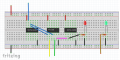
Just to follow up from this, I completed my breadboard in Fritzing and ended up with this, would be very thankful if somebody told me if I was correct or not.

upload_2016-12-16_3-5-36.png
 

MrAl

Joined Jun 17, 2014
13,751
Hello,

You did not label the lines so i have to assume:
blue: A
brown: also A
yellow: C
green: B
(note B and C can be reversed and that would be ok).

If that is the case it looks good.

Just some small notes:
1. The 74xx08 gate should be of the same logic family as the others.
2. You might want to check the output current capability of the logic gates that drive your LEDs. You have a 220 ohm resistor in series with each LED, meaning that the target current might be roughly (5-1.5)/220=16ma for the red LED. However, the LS series of TTL usually put out a VERY small current in the HIGH state, so the LED in this case would most likely light up very very dim. That's why LEDs driven with TTL are usually driven with the LOW output state rather than the high because the current in the LOW state is almost always much greater, possibly by a factor of 20. I dont know if you will loose points for this because technically it is not a workable design as is, although the logic looks perfect now. Perhaps some buffers for the two LEDs and you'll be all set :)

Dont loose hope though, as you do more of these it gets easier and easier. You said you were absent for part of the course so it makes sense that you are having trouble now. Who wouldnt? Once you get some practice in, you'll be doing this with little effort. Logic is usually easier than Analog :)
 
Top