How to go from truth table to circuit schematic and then breadboard?

djsfantasi

Joined Apr 11, 2010
9,237
So I can see that they are not the same, so back to my initial part of A'B + A'C + A.

Would this be represented in a circuit diagram with
by having the first A' go through an inverter to an AND gate, B also going to the same AND gate. Then the 2nd A' to a seperate AND gate and C to the same gate. And then finally A on it's own goes directly in to a seperate AND gate, and then all of these go to one OR gate at the end?

Is this the best way to do it or am I able to fit all inputs in to one AND gate?
In general, your description is correct. The Boolean function for the LED uses two AND gates and so should your circuit.

I do have one question. Where did the third term come from? It seems to have mysteriously appeared. Once again, I suggest checking your expression with a truth table. You need to be more careful.
 

Thread Starter

Jamie Kyle Thomas

Joined Dec 9, 2016
24
Hi,

Yes that looks good :)

See how simple this gets now (as i think you have spotted the simplification for the Green LED)?

There is a catch however, and that is the assignment question seems to be asking for you to perform specific tasks one step after the other. First [1] they want the truth table (which you have accomplished), and then [2] they want the logic statements, and then [3] they want the reduction of those statements, and then finally [4] they want the logic circuit using standard gates.
So you have completed step 1, and for step 2 you probably have to do the full logic statement for the Green LED and Red LED where you include all three inputs ABC in the statements, then for step 3 show how you reduce those statements from step 2, then for step 4 show the circuit.
So for a quick example of step 2 for the Green LED (the simpler one) we would probably have to see at first:
C'B'A+C'BA+CB'A+CBA

and then for step 3 show how you reduce these to get the single A statement. That seems to be part of the assignment.

BTW, bit A is the odd/even bit and that's true for any number of binary bits. A typical test for odd or even integer in a language like C or C++ is to use the logical AND function to mask out the other bits and then see if the result is zero or non zero.

As for choosing the logic gates, do you know how a statement like AB converts to an AND gate and A+B converts to an OR gate for example?

Hello MrAl, very happy to get another response from you, you're really helping me.

Now you're correct in saying I have to do this in steps, I have the Green LED and Red LED both done with their elongated logic statements and now I am on the process of simplifying them down to their lowest form before I try to put them in to a circuit diagram.

> As for choosing the logic gates, do you know how a statement like AB converts to an AND gate and A+B converts to an OR gate for example?

I do understand this part, thankfully for now I only have to use AND and OR gates.

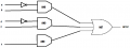
Would I be right in saying A'B would have a wire coming from A', through an inverter, then to an AND gate, and then B going to that same gate? Same for A'C then and then A at the end directly goes in to said and gate? or should I use multiple gates? (one for each input)

What I have right now is A'B + A'C + A. I tried simplifying this further to A'BC + A but that doesn't seem to work. I've included a small diagram of my first attempt at putting this in to a circuit diagram.

upload_2016-12-15_13-3-43.png
 

djsfantasi

Joined Apr 11, 2010
9,237
As for choosing the logic gates, do you know how a statement like AB converts to an AND gate and A+B converts to an OR gate for example?

I do understand this part, thankfully for now I only have to use AND and OR gates.

Would I be right in saying A'B would have a wire coming from A', through an inverter, then to an AND gate, and then B going to that same gate? Same for A'C then and then A at the end directly goes in to said and gate? or should I use multiple gates? (one for each input)

What I have right now is A'B + A'C + A. I tried simplifying this further to A'BC + A but that doesn't seem to work. I've included a small diagram of my first attempt at putting this in to a circuit diagram.

View attachment 116920
You asked how a statement like AB converts to an AND gate. That is what it represents. There is no "how". AB means A AND B. The same statement applies to A+B. It means A OR B.

There is one point in your earlier diagram. When there is only one input, such as A, there is no need to go through the AND gate. You would wire it directly to the OR gate.

I still urge you to verify that the expression A'B+A'C+A is actually what you want.
 

Thread Starter

Jamie Kyle Thomas

Joined Dec 9, 2016
24
You asked how a statement like AB converts to an AND gate. That is what it represents. There is no "how". AB means A AND B. The same statement applies to A+B. It means A OR B.

There is one point in your earlier diagram. When there is only one input, such as A, there is no need to go through the AND gate. You would wire it directly to the OR gate.

I still urge you to verify that the expression A'B+A'C+A is actually what you want.
So on my diagram A does not need to go through an AND gate (I see why now) and goes directly to NOT, so I can change that.

I'm guessing from your last comemnt that you've spotted an error in me calculating my final expression, could you point me to where I have gone wrong.

I've tried simplifying it but the truth tables didn't match (maybe I did them wrong)
 

Thread Starter

Jamie Kyle Thomas

Joined Dec 9, 2016
24
In general, your description is correct. The Boolean function for the LED uses two AND gates and so should your circuit.

I do have one question. Where did the third term come from? It seems to have mysteriously appeared. Once again, I suggest checking your expression with a truth table. You need to be more careful.
Sorry I missed this when replying to your last comment. If by thrid term you are refrencing the A. From my Karnaugh map for the Red LED I got A'C + A'B and then from my green I just ended up with A.

I just re did my truth tables for A'C + A'B and it seems they are actually the same, so am I right in thinking this can be simplified to A'CB?

So my final expression would be A'CB(RED LED) + A (GREEN LED)

Sorry if it seems I'm not being careful but I am extremely new to this
 

djsfantasi

Joined Apr 11, 2010
9,237
Ok, I see your logic. But what I don't understand is that it looks to me that you are combining the outputs for the red and green LEF into one statement. Is that what you want? Or do you want two separate outputs?
 

Thread Starter

Jamie Kyle Thomas

Joined Dec 9, 2016
24
Ok, I see your logic. But what I don't understand is that it looks to me that you are combining the outputs for the red and green LEF into one statement. Is that what you want? Or do you want two separate outputs?
I need to eventually put these statements on to a breadboard as the final part of the work. I also need to provide a circuit diagram. I'm not 100% sure if I need 2 outputs or one as it doesn't specify in the document attatched to the initial post.

Can you confirm if A'C + A'B = A'CB?
 

WBahn

Joined Mar 31, 2012
33,067
Sorry I missed this when replying to your last comment. If by thrid term you are refrencing the A. From my Karnaugh map for the Red LED I got A'C + A'B and then from my green I just ended up with A.

I just re did my truth tables for A'C + A'B and it seems they are actually the same, so am I right in thinking this can be simplified to A'CB?

So my final expression would be A'CB(RED LED) + A (GREEN LED)

Sorry if it seems I'm not being careful but I am extremely new to this
You've got a couple of misconceptions.

You actually have TWO problems you are trying to solve. You need a circuit that drives the Green LED. That circuit turns that LED on whenever signal A is HI. You also happen to need a circuit that drives the Red LED. That circuit turns that LED on whenever signal A is LO and either signal B or C are HI. These are two different signals. One signal to drive the Green LED and one signal to drive the Red LED. You can't combine them because the need to be HI and LO for different combinations of the input signals.

As for whether A'C + A'B is the same as A'CB, just ask about a simple case. For instance, if B is LO, then there is no way for A'CB to be HI. But if B is LO, then A'C + A'B can still be HI if A is LO and C is HI. So these are not the equivalent expressions. In Boolean algebra you can "factor out" a common term so

A'C + A'B = A'(C + B)

It seems like you should review the basics of Boolean algebra as you have some gaps in the fundamentals. This might help:

http://www.allaboutcircuits.com/technical-articles/boolean-basics/
 

Thread Starter

Jamie Kyle Thomas

Joined Dec 9, 2016
24
You've got a couple of misconceptions.

You actually have TWO problems you are trying to solve. You need a circuit that drives the Green LED. That circuit turns that LED on whenever signal A is HI. You also happen to need a circuit that drives the Red LED. That circuit turns that LED on whenever signal A is LO and either signal B or C are HI. These are two different signals. One signal to drive the Green LED and one signal to drive the Red LED. You can't combine them because the need to be HI and LO for different combinations of the input signals.

As for whether A'C + A'B is the same as A'CB, just ask about a simple case. For instance, if B is LO, then there is no way for A'CB to be HI. But if B is LO, then A'C + A'B can still be HI if A is LO and C is HI. So these are not the equivalent expressions. In Boolean algebra you can "factor out" a common term so

A'C + A'B = A'(C + B)

It seems like you should review the basics of Boolean algebra as you have some gaps in the fundamentals. This might help:

http://www.allaboutcircuits.com/technical-articles/boolean-basics/
Okay I see why I need 2 circuit diagrams. I've reviewed the article you linked also. Unfortunately the pressure is really getting to me with this deadline tomorrow drawing nearer and I'm worried that I'm even struggling to grasp the basics. Definitely need to do more research on boolean logic over Christmas as I'm like a duck out of water right now.

I know you're trying to guide me in the correct direction without giving too much away, but do you think you could reveal a bit more?

I know my final expression should be A'(C + B) for the red LED and just A for the green LED. But i'm struggling to put these in to the context of 2 circuit diagrams. Do I include A' in my diagram? I have looked at a few tutorials and I can't find my answer.

Best I have right now is C + B going in to an and gate then to an OR gate for red, and then seperately A going in to a not gate for Green, but I guess these are wrong too.
 

djsfantasi

Joined Apr 11, 2010
9,237
Let's ignore the circuit for the green LED. It's just A and is simpler than the circuit for the red LED.

So you have the logic A'B+A'C for the red LED. Chunk the problem down. A circuit for A' looks like what? Then, using that circuit, what does A'B, or A' AND B, look like? Apply the same approach for A'C. Now you have two outputs that must be sent through an OR gate. The final result of all these building blocks is what turns on your red LED.
 

djsfantasi

Joined Apr 11, 2010
9,237
That doesn't mean one circuit. Just one diagram. Depending on the detail your professor expects, many elements of a working circuit are shared - specifically the power supply including the signal ground. And the signal A is also shared.

Just don't want you to get stuck over this detail.
 

Thread Starter

Jamie Kyle Thomas

Joined Dec 9, 2016
24
That doesn't mean one circuit. Just one diagram. Depending on the detail your professor expects, many elements of a working circuit are shared - specifically the power supply including the signal ground. And the signal A is also shared.

Just don't want you to get stuck over this detail.
Thanks.

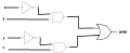
This is what I have based off your other comment, can you let me know if I have gone wrong?

upload_2016-12-15_16-27-33.png
 

WBahn

Joined Mar 31, 2012
33,067
Okay I see why I need 2 circuit diagrams. I've reviewed the article you linked also. Unfortunately the pressure is really getting to me with this deadline tomorrow drawing nearer and I'm worried that I'm even struggling to grasp the basics. Definitely need to do more research on boolean logic over Christmas as I'm like a duck out of water right now.

I know you're trying to guide me in the correct direction without giving too much away, but do you think you could reveal a bit more?

I know my final expression should be A'(C + B) for the red LED and just A for the green LED. But i'm struggling to put these in to the context of 2 circuit diagrams. Do I include A' in my diagram? I have looked at a few tutorials and I can't find my answer.

Best I have right now is C + B going in to an and gate then to an OR gate for red, and then seperately A going in to a not gate for Green, but I guess these are wrong too.
(C + B) is the expression for a logical OR of C and B, not an AND. So these two signals go into a 2-input OR gate.

What you have is

A'(C + B) = (A')(C + B) = XY

where

X = A'
Y = C + B

A' is just NOT A (hint, use an inverter)
C + B is just (C OR B)
XY is just (X AND Y)
 

Thread Starter

Jamie Kyle Thomas

Joined Dec 9, 2016
24
(C + B) is the expression for a logical OR of C and B, not an AND. So these two signals go into a 2-input OR gate.

What you have is

A'(C + B) = (A')(C + B) = XY

where

X = A'
Y = C + B

A' is just NOT A (hint, use an inverter)
C + B is just (C OR B)
XY is just (X AND Y)
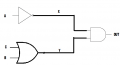
Could you check the diagram I have posted above and let me know if this is correct?

Is the further simplification of said diagram below?

upload_2016-12-15_17-19-50.png
 

djsfantasi

Joined Apr 11, 2010
9,237
To combine these two then, would I directly run A to the same OR gate that A'B + A'C is going to?
Sigh... why do you keep insisting on combining the two logical cases??? Your problem has two outputs (a red LED and a green LED). You don't OR them together, nor do you AND them together. They turn on different LEDs, so must be kept separate.
 

Thread Starter

Jamie Kyle Thomas

Joined Dec 9, 2016
24
(C + B) is the expression for a logical OR of C and B, not an AND. So these two signals go into a 2-input OR gate.

What you have is

A'(C + B) = (A')(C + B) = XY

where

X = A'
Y = C + B

A' is just NOT A (hint, use an inverter)
C + B is just (C OR B)
XY is just (X AND Y)
Could you check the diagram I have posted above and let me know if this is correct?


Sigh... why do you keep insisting on combining the two logical cases??? Your problem has two outputs (a red LED and a green LED). You don't OR them together, nor do you AND them together. They turn on different LEDs, so must be kept separate.
So what you're asking me is why am I doing it wrong? Probably because I know no better, the exact reason I am posting here in the first place.

So I'll continue with thos diagram for RED


and then for Green I just need A, how would I represent that?
 

djsfantasi

Joined Apr 11, 2010
9,237
I'm lost... Some of your questions appear to demonstrate a total lack of understanding.

Before I go on, I have one clarification regarding your diagram. It does not specify what the output is used for. I would have labelled it "Red LED" instead of "OUTPUT". Perhaps if you make that change, it will become more obvious what the next step should be.

You ask, how do you represent just A?

Look at your last diagram. You have two nodes labelled A. Focus on the top one. You need to invert the signal, and you have an inverter. So what do you do with the diagram regarding signal A and the inverter?

Pausing...

You drew a line between them.

Now you have the signal A and you want to do what with it? What will it's function be? And how are you going to connect them? Remember the suggestion I made in my opening paragraph.
 
Top