How to generate a short pulse(5~50ms) when a switch is on

Thread Starter

garudaone

Joined Nov 22, 2022
16
Hi,

I have a water level sensor is NO/NC type which will disconnect when water is full and connect when water is empty and I want to send a short pulse when water is full and when it's empty.

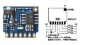
I have a RF433 module which has 2 keys. If I connect a key to VCC, it'll send a code to its receiver. However, if I keep it connected, it'll keep sending signal which will consume battery.
So I want to only connect the the key to VCC for a short time when the sensor is connected and the other key to vcc when the sensor is disconnected.

I know it's easily done with a microcontroller, however I want a more simpler approach.

Thanks;
 

crutschow

Joined Mar 14, 2008
34,408
What is Vcc and the signal voltages?
How long is a "short pulse"?

It could likely be done with a XOR gate connected to give a pulse when the input goes high, and a pulse when the input goes low.
Or do you need to differentiate between the high and low pulse?
 

crutschow

Joined Mar 14, 2008
34,408
Here's the XOR function made with one quad, 2-input, Schmidt-trigger NAND gate package to avoid the possible oscillation problem with slow rise and fall time input signals while generating a pulse on both the rise and fall of the input.

1669180679167.png
 
Last edited:

Thread Starter

garudaone

Joined Nov 22, 2022
16
Here's the XOR function made with one quad, 2-input, Schmidt-trigger NAND gate package to avoid the possible oscillation problem with slow rise and fall time input signals while generating a pulse on both the rise and fall of the input.

View attachment 281247
I need to send the pulse to another key when it's disconnected(K1).
 

Attachments

Thread Starter

garudaone

Joined Nov 22, 2022
16
What is Vcc and the signal voltages?
How long is a "short pulse"?

It could likely be done with a XOR gate connected to give a pulse when the input goes high, and a pulse when the input goes low.
Or do you need to differentiate between the high and low pulse?
Yes, I need a different pulse. When it's on, i send to K1 and K2 when it's off. Please refer to this attached image of the rf433 module
 

Attachments

crutschow

Joined Mar 14, 2008
34,408
When it's on, i send to K1 and K2 when it's off.
Okay.
Below is the LTspice simulation of a circuit to generate the two separate pulses:
It uses one CD4093 quad, 2-input, Schmidt-trigger NAND package, plus a few resistors and capacitors.
The circuit will operate with a supply voltage of 3V-15V.
You can tweak the values of the two 50k ohm resistors if you want to change the pulse time.

1669269342900.png
 
Last edited:

Thread Starter

garudaone

Joined Nov 22, 2022
16
Okay.
Below is the LTspice simulation of a circuit to generate the two separate pulses:
It uses one CD4093 quad, 2-input, Schmidt-trigger NAND package, plus a few resistors and capacitors.
The circuit will operate with a supply voltage of 3V-15V.
You can tweak the values of the two 50k ohm resistors if you want to change the pulse time.

View attachment 281278
Thank you very much. This is the optimal solution I want. I will acquire CD4093B as soon as possible.
 

AnalogKid

Joined Aug 1, 2013
11,036
Below is the LTspice simulation of a circuit to generate the two separate pulses:
Won't the series capacitors couple switch bounce to the output? The module chip probably has debouncing built into its firmware. But if not, this could be an operational issue.

Same for the circuit in post #10.

ak
 

Thread Starter

garudaone

Joined Nov 22, 2022
16
And that is what my circuit does.
You don't need the 4093 if the switch in the sensor is a SPDT relay contact.
You didn't post a link to the sensor so I don't know for sure.
Thank you very much. Yours really works. I just tested with my Rf433 module.


I also have another water pressure switch. It's just on/off switch, which will disconnect if pressure is high. I also want to have a pulse when it's connected and another different pulse when it's disconnected. Can you help me on this?
 

sghioto

Joined Dec 31, 2017
5,388
I think the encoder chip has debounce because the wiring diagram shows push button switches for K1-K4
 
Last edited:

sghioto

Joined Dec 31, 2017
5,388
I also have another water pressure switch. It's just on/off switch, which will disconnect if pressure is high. I also want to have a pulse when it's connected and another different pulse when it's disconnected. Can you help me on this?
This circuit works on the bench with a few more parts including Q1.
1669305622076.png
 

shell.albert

Joined Jul 23, 2014
21
If the switch in the water sensor is a SPDT type this configuration should work. The value of C1 and C2 will determine the pulse time.
Do you have a link to the water sensor?
View attachment 281290
Hi guy. This is your circuit simulation result.
Since the pulse time is very short, and the amplitude is not very high. I think you should an additional circuit behind to rectify the wave, something like a GATE logic nor complicated like a voltage comparator with a low threshold settings.

simu.png
 

sghioto

Joined Dec 31, 2017
5,388
I think you should an additional circuit behind to rectify the wave, something like a GATE logic nor complicated like a voltage comparator with a low threshold settings.
Additional circuitry not required as the TS confirmed the circuit works in post 15 and 18. I appreciate the analysis but what you have simulated using R31 at 10K I don't think represent the input impedance of the EV1527 encoder chip. I haven't been able to find any data on the actual value of the internal pull down resistors but there is a 4.7K series resistor on each input on the pcb.
Try the simulation again with R31 set at 47K and even 100K.
 
Top