How to drive many LEDs for large display clock?

Thread Starter

Bryan Murphy

Joined May 1, 2020
17
Hello there! I hope that you are all keeping safe wherever you are.

Here's my problem:

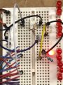
I'm a Physics teacher in England and thought that it would be interesting and fun to make a huge digital clock as a wall feature. I bought a C51 4 bit clock from ebay for practically nothing, and thought that I could make it drive a bank of leds. Each of the 29 elements would go straight to their own 4N25 optoisolator, then I thought that I could take the other side and connect it to the base of a 2N2222 transistor, through a 1kohm resistor, capable of driving 0.5A This should be fine for 20 0.02A red leds I thought. So I made a breadboard circuit to try it out. Everything went to plan, I tested it with a single led coming from (through the 4N25) a multiplexing common cathode and the anode from the second flashing decimal point. Fabulous! It worked. I then thought that it would be a piece of cake to put another 19 leds in as well. No joy, the more I added the dimmer they got. Unfortunately, with the lockdown I can't pop into work to get an oscilloscope to see what's going on. Ohm has a lot to answer for!!

Anyway, anyone one out there who could jot down the circuit for the output side of the 4N25 to give me 20 beautiful dazzlingly bright 20mA leds and put me out of my misery?

Thanking you in advance!!
 

danadak

Joined Mar 10, 2018
4,057
"Normally" you would buffer the segments with a driver. I assume you have
several LEDs/segment, best if they are wired in series and your 2N2222 drives
them as a series string. Is clock output 4 bit BCD or Binary ? Which means you would
need a decoder to decode 4 bit to 7 segment.


Regards, Dana.
 

Papabravo

Joined Feb 24, 2006
21,159
A schematic of what you have would be helpful. It sounds like all your available current is going through a single path which is current limited.
 

ci139

Joined Jul 11, 2016
1,898
No joy, the more I added the dimmer they got.
it may have to do with the "sink" capability of the single 2N2222 -- the more I.c the higher the V.ce (see Fig.4) (LED-s in their "emission" zone are higly dependent on voltage)
you can try to increase the base current of the 2N2222 (up to it's d/s limit) or use more powerful "switch" ? mosfet . . . if it's multiplexed you may want to add an apx. 10nF or a reverse diode in parallel to LED-s
 
Last edited:

Audioguru again

Joined Oct 21, 2019
6,673
You say the load was 400mA and the 2N2222 transistor has a 1k base resistor. You need the transistor to saturate then its datasheet says that its base current must be at least 40mA (1/10th the collector current). Then you need 42V feeding the 1k base resistor.
Also, the datasheet for the 2N2222 shows that it is a weak little transistor that works poorly as a 400mA switch so its voltage loss causes it to heat up and that wasted power is subtracted from the power to the load.

Depending on the power supply voltage, a logic-level Mosfet would work fine without the problems caused by the 2N2222.
 

dl324

Joined Mar 30, 2015
16,846
Welcome to AAC!
I bought a C51 4 bit clock from ebay for practically nothing
What is a C51 4 bit clock?
Each of the 29 elements would go straight to their own 4N25 optoisolator
Why are you using optoisolators? What are the 29 elements for? All digits, one digit? 4 seven segment displays and an LED for seconds?
I tested it with a single led coming from (through the 4N25) a multiplexing common cathode and the anode from the second flashing decimal point. Fabulous!
A schematic of how you connected one LED, and then others, would be helpful.
 

Thread Starter

Bryan Murphy

Joined May 1, 2020
17
Thank you so much for your interest and suggestions. I hope that these photos explain what I am trying to do.

You see, I have taken the outputs from the clock and put them in the breadboard. The purple wires are for the switches, the blue ones for the cathodes and the red ones for the anodes. I thought that if I took 9 and 3 as the input to the optoisolator, then I could take its outputs to switch a transistor. Typically, a circuit that would give full marks at GCSE wouldn't actually work! Due to the lockdown I can't get my 'Art of Electronics' by Horovitz from school.

Audioguru, I like what you say. I'm using a 5V supply, 20W. The 29 elements are 7 for each digit and the flashing pair in the middle driven from 3 and the multiplexing (I guess) 9. I just want a semiconductor to work like a relay; either open or closed.

The led in the photo is flashing merrily, then I tried all sorts of combinations of more in series and parallel, but as I said they just got dimmer. I think I'm asking too much of the transistor, and my naive assumption that it acts as a switch and when saturated can deliver 0.5A is completely wrong. I should study that data sheet until I understand it.

Anyway, one of you nice clever people could help me out, and I would be eternally grateful if you could jot down and send me a circuit that I could use. Mosfet eh? I'll have a look. I bought a bag of 2N2222s. Anyone want them?!!

There's no rush. This lockdown looks as if I won't be back in the classroom before September, but Teams and Google Classroom's keeping me very busy.

I'm going to make the big box on the laser cutter, I want each element of each number to have say 16 or so leds, like the attached photo.

Thanks again,

Bryan


96028045_634647490417802_8611171826594217984_n.jpg

95920152_274180243609692_7528433111260987392_n (1).jpg

95574403_2082153028594896_8418736778969612288_n.jpg

clock.jpg
 

Attachments

Thread Starter

Bryan Murphy

Joined May 1, 2020
17
danadak, Papabravo, ci139, Audioguru and dl324,

Thanks for getting me thinking about this properly and ci139 for the suggestion of a mosfet. Why didn't I think of that? A few YouTube videos later and a BS170D272 in a TO-92 package should do the job. Nothing ridiculous, no heatsink needed, cheap as anything.

Cheers!
 

Audioguru again

Joined Oct 21, 2019
6,673
The datasheet for a 2N2222 shows that with a load of 500mA and a base current of 50mA, its saturation voltage loss (from the collector to emitter) is 1.6V max which is subtracted from the 5V supply for the LEDs making them a little dim. If the transistor does not have a base current that high then it turns on less and the LEDs will produce no light. The circuit driving the 2N2222 cannot produce the 40mA of base current fore your 400mA load so the 2N2222 will not work anyway.

A logic level Mosfet does not need any current to turn on (like a mechanical switch) producing no voltage loss for feeding the LEDs.

The little Mosfet you selected is not logic level so it needs a 10V gate-source voltage to fully turn on. When it does turn on its max resistance is 5 ohms which causes a 2V loss from the 5V feeding the LEDs and causes the Mosfet to smoke and burn.
I would use an IRL540 power Mosfet, but smaller ones might be available..
 

dl324

Joined Mar 30, 2015
16,846
Anyway, one of you nice clever people could help me out, and I would be eternally grateful if you could jot down and send me a circuit that I could use.
Are you planning to use several discrete LEDs per segment? In that case, you'd need multiple LEDs in parallel.

I read the current limit resistor as 47 ohms. That would give a current of 3X what the LED is probably rated for.
 

ci139

Joined Jul 11, 2016
1,898
To likely-ensure that you would not be needing any extra heat sinking choose I.collector or I.drain (continuous) at least 3x larger than your average current draw
+
? How you drive your opto . . . these have iR LED-s that usually drop 1.4÷1.8V compared to RED-LED's 1.8 to 2.2 V https://www.electronics-tutorials.ws/blog/optocoupler.html
https://www.vishay.com/docs/83725/4n25.pdf ← typical is 1.3V . . . notice the NCTR(SAT) at Fig.2 to Fig.5 & Fig.8 = the current transfer ratio depends on I.F.LED + the dark (thermal base-) current makes the output transistor more open at higher temperatures . . . the turn on/off Fig.12 Fig.13 set usually below 80kHz speed limit
https://www.vishay.com/docs/84256/useoptocouplerdatasheet.pdf
 
Last edited:

Thread Starter

Bryan Murphy

Joined May 1, 2020
17
Thanks Dennis. Yes, you are right! This was the one to hand, and I thought that with the led being on for only 1/4 of the time, it should cope.
 

dl324

Joined Mar 30, 2015
16,846
Thanks Dennis. Yes, you are right! This was the one to hand, and I thought that with the led being on for only 1/4 of the time, it should cope.
You're right.

Here's a suggestion:
clipimage.jpg

It shows the LED A and B for the 1 minute digit.

You connect the segment wires directly to the comparator inputs. R1 and R2 set the threshold that switches the comparators to 0.45V. When an LED from the clock is off, the comparator output will be LOW and that LED driver will be off. When an LED from the clock is on, the corresponding comparator output will be HIGH and the corresponding transistor will turn.

You connect the digit cathode wires directly to the corresponding MOSFET gate, one for each digit.

If you want multiple LEDs per segment, you need to connect them in parallel with the one shown. The base current in the transistor needs to be 0.1Ic, you should switch to an N channel MOSFET instead of a transistor because the comparator is only guaranteed to sink about 6mA.

The circuit will require 8 comparators (7 segments and the colon) in two 16 pin DIPs, 5 P channel MOSFETs, 7 2N2222, a bunch of resistors, and some decoupling capacitors.
 

dl324

Joined Mar 30, 2015
16,846
I see that you have 16 LEDs per segment, so you can't use 2N2222 if you want the current in each LED to be 60mA; because the comparators can't sink enough current.

Here's an updated schematic:
clipimage.jpg

Since you have 16 LEDs per segment (didn't notice that's what you were showing), you can try to use 8 strings of 2. Each of the N MOSFETs will need to handle 480mA and the P MOSFETs will need to handle 3.36A. The part numbers I showed will handle those currents, but they're surface mount (SOT-23).

EDIT: It just occurred to me that you'll probably need pulldown resistors on the non-inverting comparator inputs; 10k.

EDIT: Cleaned up component designator sequence.
 
Last edited:

Thread Starter

Bryan Murphy

Joined May 1, 2020
17
Oh Dennis, that is beautiful. It took me a bit of time to work your circuit out, but now I see how it works. What I thought was a really easy project has turned out to be not quite so. 'The Art of Electronics' indeed! Thanks
 

dl324

Joined Mar 30, 2015
16,846
It took me a bit of time to work your circuit out, but now I see how it works.
Just ask if you have any questions.

You might not need the comparators if the signal driving the LEDs switches between the power rails. Without the comparators, you wouldn't need the pull down resistors I mentioned.

You didn't post any information for the colons, so I assumed it was the same as the rest. The pinout for the display didn't show any colons.
 

Thread Starter

Bryan Murphy

Joined May 1, 2020
17
Thanks again. Yes, that's what I wanted the oscilloscope for. I'm praying that they do. If it's any hint, the output from the optoisolators seems to be off or on, at least the 2N2222 seems to think it is.
I also have a little drawer of mosfets at work too, so I could experiment with one of them before I go off and buy dozens.
Once you start actually making circuits, the theory exponentially rises to the level of pretty tricky.
 
Top