How to determine the inductance of a coil ?

Thread Starter

q12x

Joined Sep 25, 2015
2,245
Nice circuit Danko ! Bravo. I am really doing this for the first time and this is very helpful. Keep it this way and we will be friends.
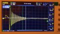
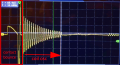
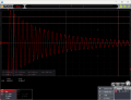
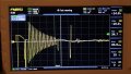
So, here is the real result, again I had to search for this oscilogram to appear on the screen, but after 5-10 tries, I got it and center it.
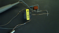
20241108_031031.jpg20241108_025902.jpg
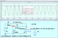
So I got between the green markers 5.84kHz and 16 peaks. How do I put this into the equation?
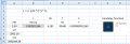
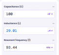
Aaand I have the calculator now, and voila _ the results are... still wrong.
1731029676862.png
 
Last edited:

Art Vandelay

Joined Nov 1, 2024
140
Nice circuit Danko ! Bravo. I am really doing this for the first time and this is very helpful. Keep it this way and we will be friends.
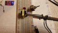
So, here is the real result, again I had to search for this oscilogram to appear on the screen, but after 5-10 tries, I got it and center it.
View attachment 335357View attachment 335358
So I got between the green markers 5.84kHz and 16 peaks. How do I put this into the equation?
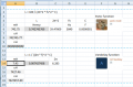
Aaand I have the calculator now, and voila _ the results are... still wrong.
View attachment 335363
5.84 kHz * 16 = 93.44 kHz
if inductor value is 2.5 mH, then
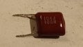
capacitor value should be about 1nF. Check your capacitor.

View attachment 335366
https://www.omnicalculator.com/physics/resonant-frequency-lc
I put the ruler on the screen in post #63 and measured one cycle. Adjusting for my screen size, the resonant frequency worked out to about 93kHz.

Are you absolutely sure everything is hooked up right? This is nearly 10 times the computed frequency for a 100nF cap and 2.5mH inductor. Maybe your scope isn't calibrated.
 

Thread Starter

q12x

Joined Sep 25, 2015
2,245
I modified my Excel calculator and leave only Vandelay function.
And just for test, I inserted your 1.16nF and it is indeed give me the 2.50mH. Again, just for test and also to check the formula.
1731062875339.png
Are you absolutely sure everything is hooked up right?
yes, I am. I showed you the screenshots for my last setup exactly as mister Danko and Vandelay suggested. Also measured the capacitor and showed you its marking. It is not the capacitor. It might be something that we are clearly blind and missing it completely.
I suggest to mister Danko to perform this setup, its not that hard, take some pictures and show me how you build it, how different than mine and with the correct oscilogram reading. Its a thought.
 

Thread Starter

q12x

Joined Sep 25, 2015
2,245
Just another test, to check it's consistency:
20241108_130614.jpg 20241108_130503.jpg
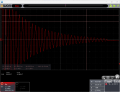
I got again 16peaks but with 14.6kHz (last time was 5.84kHz) so it's definitely something from the switch? maybe?
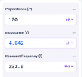
So 14.6kHz * 16 = 233.6 kHz
and now I get (https://www.omnicalculator.com/physics/resonant-frequency-lc)
1731064484420.png
So it's a bit of tolerance from 93.44 kHz last time to 233.6 kHz this time. But the result is ... somewhat? close?
where previous data was:1731064632264.png
(for comparison)
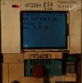
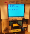
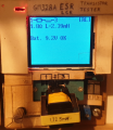
and for a moment I forget that my component tester, successfully read this particular inductor value, that is inside that E+E ferrite core. 1731066543084.png
Im getting old. So, if that can read it right, why can't we?
 
Last edited:

Thread Starter

q12x

Joined Sep 25, 2015
2,245
Switch (and breadboard?) contacts bounce.
I acknowledge what you said, confirm it and re-exemplify it. And is nice to know what is what. Its not so nice when/what we dont know it.
1731104258857.png
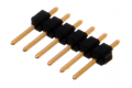
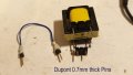
- The only reason for breadboard bounces, is when you have very skinny legs into it, like resistor legs which usually are playing loose, and when you poke the breadboard, they move and create this so called bradboard bounce. Im speaking from experience, not my ass! The breadboard itself does not create any bouncing or erroneous contacts. Only proper size legs or wire diameter and even shape, that have very firm contact will have the best connection. Like dupont pins that are square shape profile of 0.7 mm thick, those are the best to use in the breadboard holes. 1731104776793.png And my coil does have these dupont pins adapted on it (by me). The capacitor legs are thick enough and I could feel very good contact. Also my jumper wires are all good, Im using them for years and no problem from them ever. Just to clarify a few things, now that you brought up this subject.
These are dupont gold pins --scrapped-- and reused/repurposed (by me).
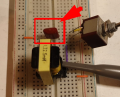
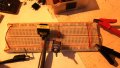
20241109_003636.jpg
With this occasion, you can see how this coil is looking under it. I even marked where is the coil and where is no contact, both on horisontal and vertical pin positions. You can actually see the enamel wire from the coil soldered to the pin and the free pins with no solder or connection bump on them. I realized this trick long after I measured a lot of these coils.
- But lets concentrate over the oscillation problem.
- I start to believe that this simple formula we used so far, it is maybe not the right one for the job? I start to wonder why my component tester is seeing the true value of it, right on, and we can not. And I start to believe that internally, in its core programming it is using different sensors and functions to automatically detect when is a simple coil in air, or a coil with magnetic core like I have here. I am guessing what it might be, I don't know for sure. But I am a programmer also (besides art) and I can do some crazy stuff in software and I know for sure its not impossible, especially that this tester can already discern between a R,C,L,mosfet, bjt, diode, led, etc. A lot of components, and this is a small miracle in 1 package. So again, I believe it can switch between different modes to read a coil, and thus , I think it is using a special formula just for coils with a magnetic core like my ferite here or even transformer steel core. who knows. I know for sure it is very versatile. So this is my impression. We are probably doing the right thing already, but not using the right key to open this door.
- Ah!! herr Danko, try to test in your spice simulator, a magnetic core coil, ideally with my parameters I used here, the 100nF cap and 2.5mH coil+ ferite core. And see if the simulator will give you the same result as before, or the same result as mine here in reality.
 
Last edited:
MrAl

Joined Jun 17, 2014
13,859
Just another test, to check it's consistency:
View attachment 335385 View attachment 335386
I got again 16peaks but with 14.6kHz (last time was 5.84kHz) so it's definitely something from the switch? maybe?
So 14.6kHz * 16 = 233.6 kHz
and now I get (https://www.omnicalculator.com/physics/resonant-frequency-lc)
View attachment 335387
So it's a bit of tolerance from 93.44 kHz last time to 233.6 kHz this time. But the result is ... somewhat? close?
where previous data was:View attachment 335388
(for comparison)
and for a moment I forget that my component tester, successfully read this particular inductor value, that is inside that E+E ferrite core. View attachment 335389
Im getting old. So, if that can read it right, why can't we?
Hi,

The resonant frequency of a 100nf cap and 2.5mH inductor is very nearly equal to 10065.8424 Hz.
As you probably know by now:
w=1/sqrt(L*C)

L*C=2.5e-10
sqrt(2.5e-10)=1.58113883e-5
1/that=63245.5532067
that/(2*pi)=10065.8424
So that is 10065.8424 Hz which is very very close to the exact frequency from the calculation.
You can expect a small deviation from that using the transient test method, but I would say not more than plus or minus 1 percent with a 10 Ohm resistor. Note if you go up in resistance the deviation will be more but shouldn't be too much as long as you don't go too high with that.
 

Danko

Joined Nov 22, 2017
2,248
I suggest to mister Danko to perform this setup, its not that hard,
take some pictures and show me how you build it,
how different than mine and with the correct oscilogram reading.
Its a thought.
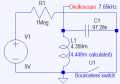
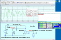
Values of L1 and C1 measured by LCR bridge meter MS5308.
1731656948152.png2024-11-15_11-24-20 - User.png
Снимок экрана 2024-11-15 063134.png
 
Last edited:
Thread Starter

q12x

Joined Sep 25, 2015
2,245
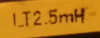
What is your real coil value written on it? I read something but Im not sure what it might be.
Is it TCZ0191 or 0344? and what do they mean?
If you are testing an unknown coil, your test is garbage, because I could do the same with the plethora of unknown coils I have and say "that is it", that value, when in reality ... is totally wrong.
Show me a clear marked coil and then the test ringing thingy.
Thanks for trying !
 

ericgibbs

Joined Jan 29, 2010
21,627
hi @q12x ,
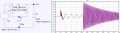
I get the same result as @Danko in simulation.
Note: the Vs is preset at 5V.
Also, the Inductor has some internal resistance, I would estimate approx 1 to 2 Ohms.
The Decay frequency is the same at 7.65kHz.

E
EG57_ 2299.png
 

Thread Starter

q12x

Joined Sep 25, 2015
2,245
My question is not about how correct the LTSpice simulation is or the equation that you run.
It is about how similar the real data is with the simulated or calculated one.
For example: My real data was the 12.5mH clearly specified on the inductor in test. 1731669091174.png I also double check this value with my prestigious GM328A meter.
1731668950037.png
Then I compare it with the tested and calculated method, that turned out very wrong, for reasons unknown yet.
But my tester here did read it right, exactly as it is mentioned on the inductor yellow band.
This send me to the conclusion we are using a wrong formula and my tester is using the correct formula- unknown to us mortals here.
-Now, going back to my friend Danko test, he just grab an inductor with no clear markings on it, test it god knows how, probably with the same setup as I did, which give me the error result, and he calls it good.
I do not believe he did it right.
Or, if I miss anything from his experiment, please clarify it for me, because now I repeated myself 2 times why I think his test is wrong.
What I was originally asking him, was to correctly duplicate my experiment. Not with the same exact inductor value, but with one that clearly shows its value and can confirm back to me that this entire osciloscope test was correct or not.
I can not be more clearer than this.
Go find a clear marked inductor, --similar-- as I have it, test it with your GM328A, or any LCR meter that will show an appropiate value of the one written on the coil. THEN, make the osciloscope experiment and the calculation and lets see what is the result then. If youre afraid you will get the same result as me, then... dont do it. Haha.
But What I really asked mister danko was to make an experiment in his LTSpice with a different formula that includes magnetic core in the coil, because this is what I highly suspect is the variable that is changing our osciloscope reading and simple calculation so far.
 

ericgibbs

Joined Jan 29, 2010
21,627
hi q12.
To check the Inductor formula, I have used a 1uF and 1mH in LTSpice, using a 5kHz test signal and the equation confirms that the inductor is 1mH

Can you explain how you are doing the test method that Danko has suggested.?
E
EG57_ 2300.png
 

MrAl

Joined Jun 17, 2014
13,859
Values of L1 and C1 measured by LCR bridge meter MS5308.
View attachment 335848View attachment 335845
View attachment 335847
Hi,

That's interesting, because there must be something unusual about the physical circuit that is not apparent from the schematic.
I say this because with a series resistor as large as 1 Megohm, there would be no ringing in that circuit at all.
The expression for the circuit to be underdamped is:
C*R^2-4*L < 0
With R so large when squared and L so small, even though C is smaller than L it would be way overdamped, which of course means no ringing. In fact, R would have to be around 423 Ohms or less to cause the circuit to become underdamped, then probably about 10 times less than that (40 Ohms) to see it really ring. That means we are not seeing something in the schematic that should be there.
It is also interesting that the measured ring frequency comes out to within about 1 percent of the theoretical when a lower value R is used. So the question becomes, what is making the circuit ring. It's not the R, L, and C alone, nor the 'step' input which looks like 5 volts. A circuit simulator should be able to confirm this, with the voltage wave across L dying down very quickly to zero.
 

MrAl

Joined Jun 17, 2014
13,859
hi q12.
To check the Inductor formula, I have used a 1uF and 1mH in LTSpice, using a 5kHz test signal and the equation confirms that the inductor is 1mH

Can you explain how you are doing the test method that Danko has suggested.?
E
View attachment 335859
It's interesting that these circuits with 1Megohm resistors in series are ringing, or at least showing that.
These circuit should not be ringing so there must be something about the simulator specs that are causing that.
I am wondering if it is because the 'switches' are not ideal. There is at least some ramp up time.
Theoretically, with R1 so huge, neither of these circuits should ring at all because they are way overdamped.
Thus, there is something not shown in either of the schematics that would explain this.

Because of this, I would suggest a much smaller series resistance be used.
 

ericgibbs

Joined Jan 29, 2010
21,627
hi Al,
In Dankos circuit he is using the 1meg resistor to give an initial charge to the capacitor ie: 5V, [which takes a little time to fully charge]
then he closes the switch which shorts across the capacitor and the inductor and of course it forms a decaying oscillatory loop.

In my sim I set the capacitor charge IC=5V then I close the discharge switch path.

E
 

Danko

Joined Nov 22, 2017
2,248
That's interesting, because there must be something unusual about the physical circuit that is not apparent from the schematic.
"Secret" of that physical circuit is in bounceless switch,
which is two crossed freshly stripped copper wires.
Between wires is gap about 1 mm.
I fast an firmly press on cross-point by fingertip and test is done.
Soft tissue of finger effectively damping wires vibration and prevents break of contact.
That's it.
When I use tumbler switch, I have oscillogram with frequency 360.75 kHz (coil self-resonance) instead 7.65 kHz:
Снимок экрана 2024-11-15 085125.png
 
Last edited:

Top